No pressure, it’s all good.

JMJ

And, we’re back! Welcome to the shop! After a brief hiatus to pour some concrete, we’re ready to set a door and some windows to enclose the garage bay. This will help keep the pollen down in the workspace, give a dehumidifier a fighting chance, and, perhaps, allow for a small window air conditioner. Workshop or man-cave, you decide. Is there really a difference?

After carefully checking the weather forecast, I judiciously selected the hottest, most humid day so far in this year to resume the engine removal. I was breaking a serious sweat just reading the manuals. All three are in general agreement, but the service manual had some extra tips that helped.

I started by siphoning as much fuel from the tank as possible. The next steps in the fuel tank removal procedure called for 5/16 inch inner diameter tubing. Of course, I couldn’t find the bits and pieces of fuel line that I’ve collected over the years, so I bought a three-foot section to get on with the job. (I found the other pieces of fuel line when I finished this task and went to put things away.) I prepared a short section of hose with a bolt plug and hose clamp as recommended in the manual. I then used a male-male hose coupling from the siphoning rig to manage the fuel that would flow from the cross-over line when separated from the tank. That tip came from Steve Housden with SIK Baggers (Housden, 2022, 9:14). Several YouTube videos showed the mechanic clamping the cross-over line (Housden, 2022, 6.56) despite the caution in the service manual against clamping or kinking this line. The cross-over line has a rigid inner lining that will be damaged if clamped. I suppose it doesn’t matter if you’re going to replace the cross-over line, but we’ll stick to the manual here. While disconnecting the fuel supply line from the tank to the engine, I found that the pressure had indeed bled off as mentioned in our previous post. Hence, the title of this post.
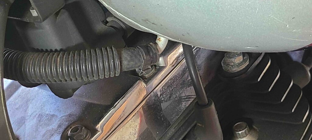
Cross-over fuel line into right-hand side of tank.

The oil from the primary chaincase was clean. As the picture below shows, everything appears normal. The chain tensioner wear pad shows a bit of wear and will likely need to be replaced. The primary chain locking tool should arrive soon and we will continue the removal process. (Note: The tool has arrived and is listed in the resources.)
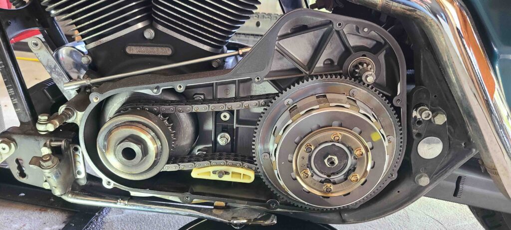
Primary chaincase cover removed

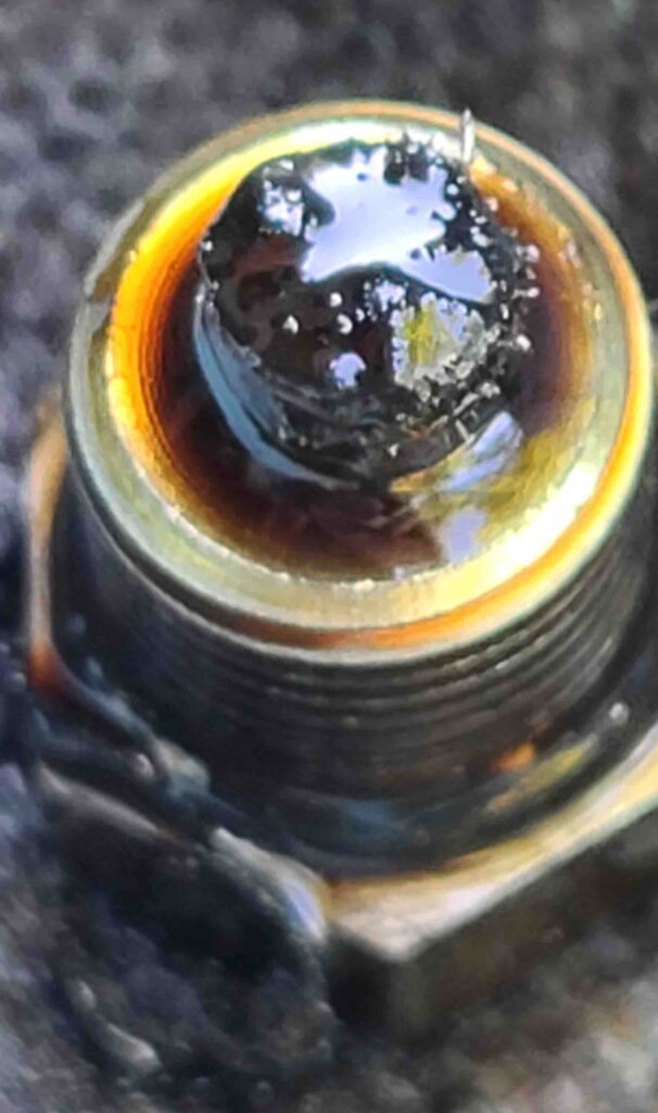
A few notes in closing. Like the engine oil drain plug, I found bits and pieces of what appears to be thread tape on the primary oil drain plug. I wasn’t expecting that with an o-ring on the plug, but I guess the last service technician felt it necessary.
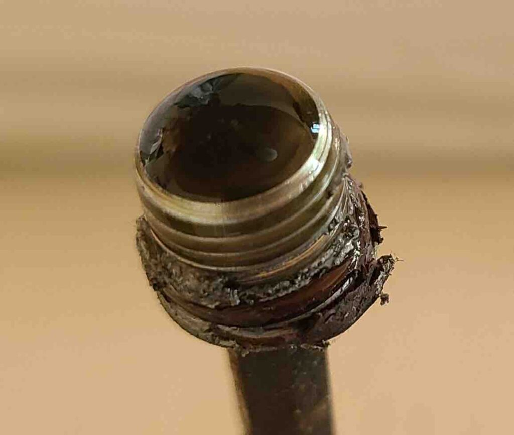
Primary chaincase oil drain plug

The Harley-Davidson special tool (HD-41771 ROTOR REMOVER/INSTALLER and SHAFT PROTECTOR SLEEVE) for pulling the rotor from the high-output alternator is scarce. The one listed on ebay did not show the protective sleeve and was very pricey. The new one offered at Jan Willem Boon (Boon, n.d.) was reasonably priced, but they don’t ship overseas. That site also showed a JIMS equivalent tool (Jims Alternator Rotor Puller Big Twin 16-1054) that shows up as out-of-stock on several websites. While writing this post, I found one that appeared to be in stock, but, alas, no. I guess we will have to make one. If all goes well, I will post a drawing with dimensions and such for posterity’s sake. We all need options, right?

Cheers!
What’s in your oil?

JMJ

Greetings! Welcome back to the shop. The motorcycle is secured in a stand with externals removed, namely, the lower fairings, saddlebags, seat, and battery. We’re starting the engine removal process by draining and straining the engine oil, mostly to satisfy my curiosity.

As expected, the oil plug has a magnetic tip. If the first clue was noise in the crankcase, the second clue was the metal shavings covering the magnet (see photo below). Syn3 oil drains really slowly when cold, so I gave it an hour to drain before re-installing the plug. The photo below shows some of the debris I found in the drain pan. After straining the oil into a jug for disposal, I pulled out the larger pieces (0.5 – 1.0 mm). Some of them appeared to be sealant or tape that was used to seal the drain plug. Other pieces are of unknown origin at this point (cam chain tensioner?). I removed and drained the oil filter as well, but found nothing new. At some point, we’ll open the filter and examine the media. We will also examine the residue in the oil pan when that is removed.

The work flow from the service manual (2004 Harley – Davidson Service Manual – Touring Models – P/N99483-04A (2004 Touring 1450-Cc 5-Speed Models), 2003) lists the following main steps.

  • Removing Engine from Chassis
  • Top End Overhaul, Disassembly
  • Bottom End Overhaul, Disassembly
  • Subassembly Service and Repair, Top End
  • Subassembly Service and Repair, Bottom End
  • Bottom End Overhaul, Assembly
  • Top End Overhaul, Assembly
  • Installing Engine in Chassis

No surprises here. The first procedure in removing the engine is the complete removal of the fuel tank. While the procedure call for purging the fuel supply line to relieve pressure, I won’t be starting the engine to do this. I have not been able to find any alternative procedure for relieving fuel system pressure, but several sources have convinced me that the pressure will have already bled off by now. We will see.

Also of note, while searching for alternative procedures, I ran across a YouTube video (Blue Collar Bike Werks [https://www.youtube.com/channel/UCFxn1rCE3rM_BLyvHz7yrtA], 2017) showing a common failure mode for the fuel pump. The theory is that the ethanol in today’s fuel accelerates the breakdown of the material used in the regulator housing at the bottom of the fuel pump. The regulator housing is held in place by two ears that can break allowing the housing to shift out of position and disrupt the fuel pressure regulation. We’ll take a look at this while the fuel tank is empty and removed.

Cheers!

The Workbench is Ready

JMJ


Greetings! I hope everyone had a happy and blessed Easter. Our family had a lot going on, so it’s nice to have a bit of a breather.

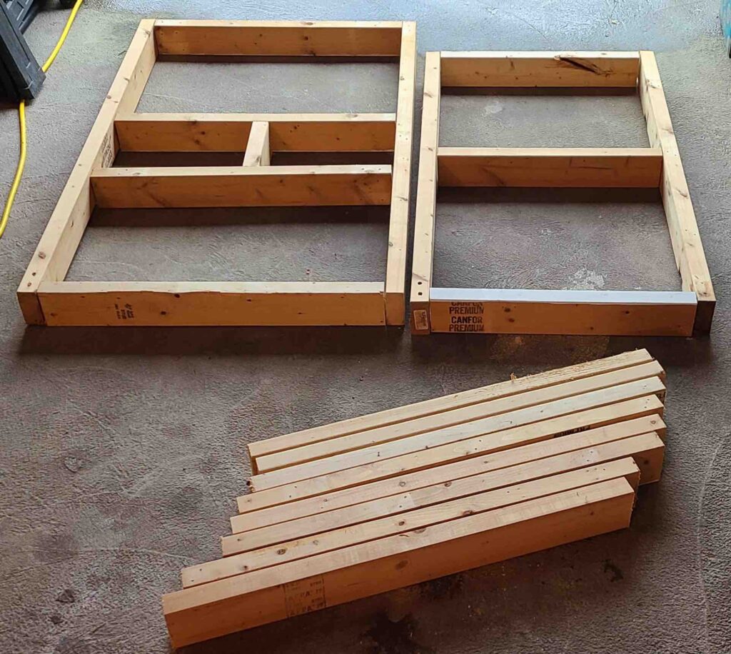
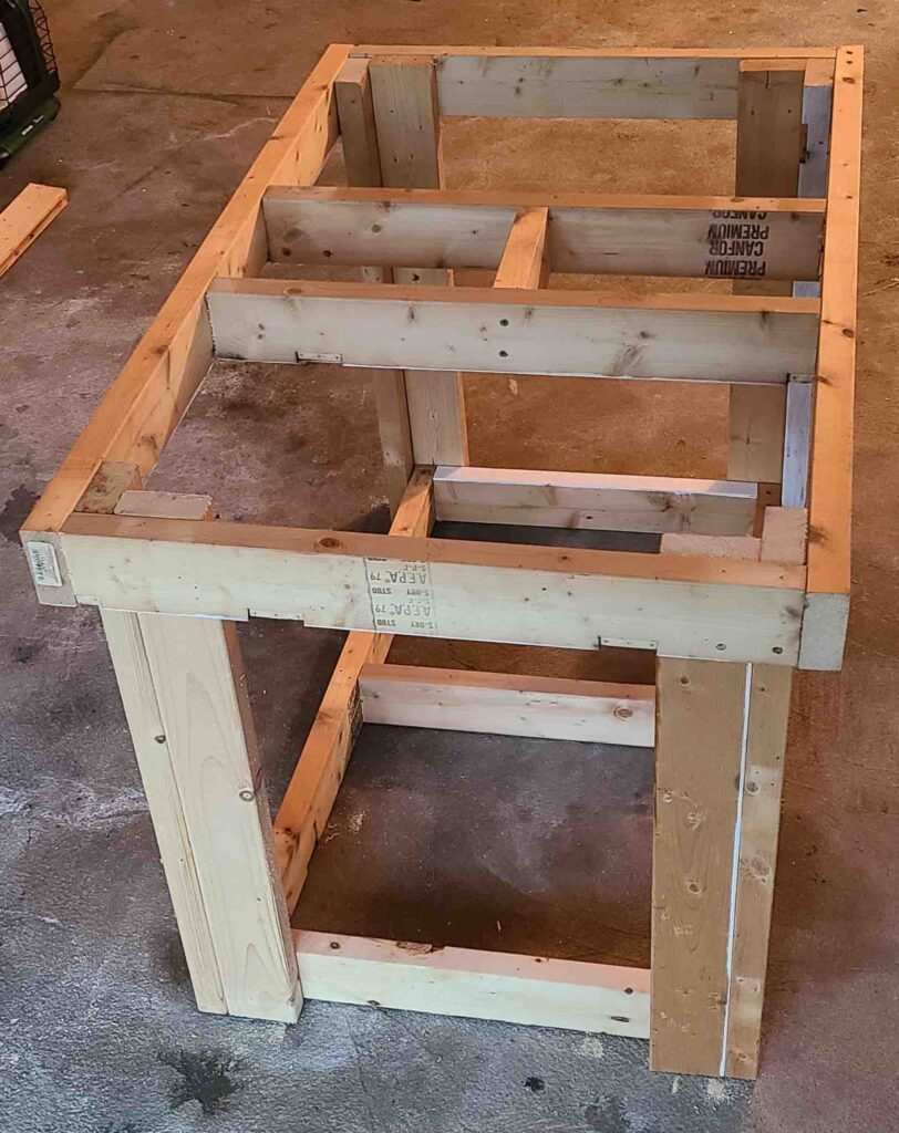
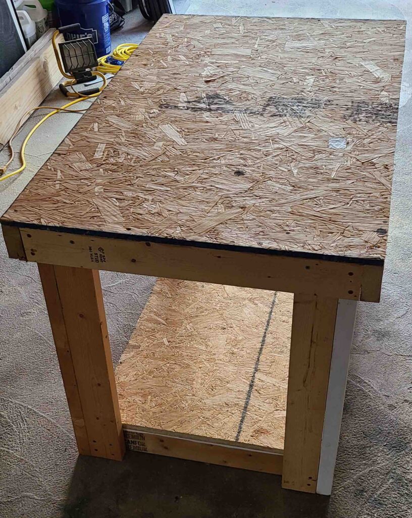
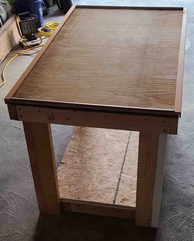
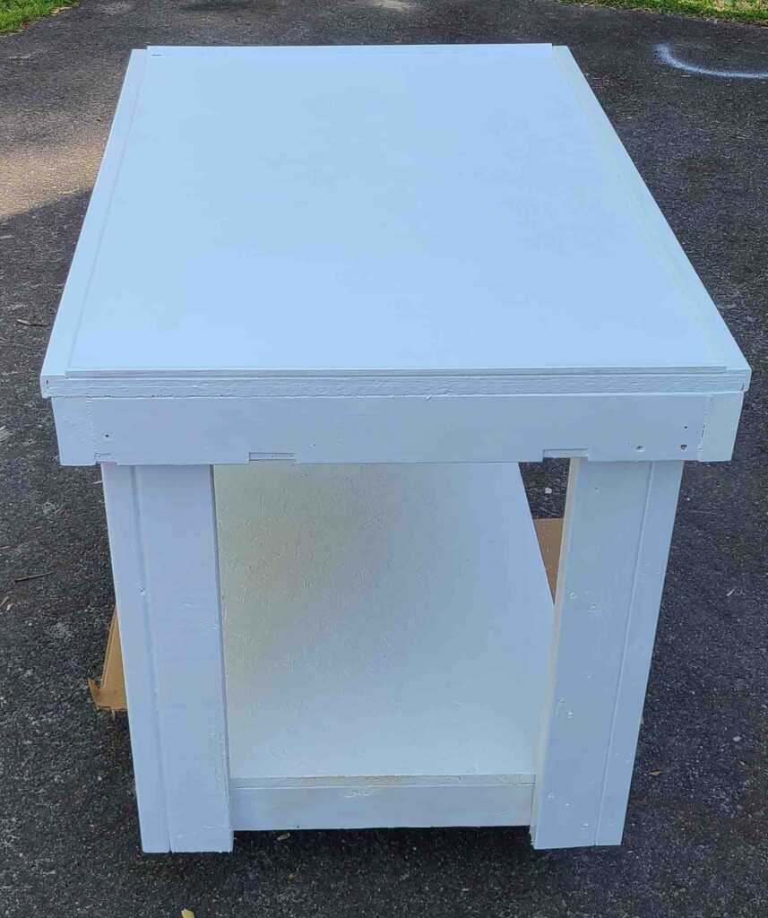
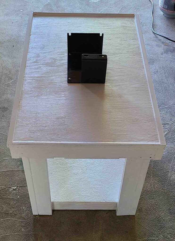
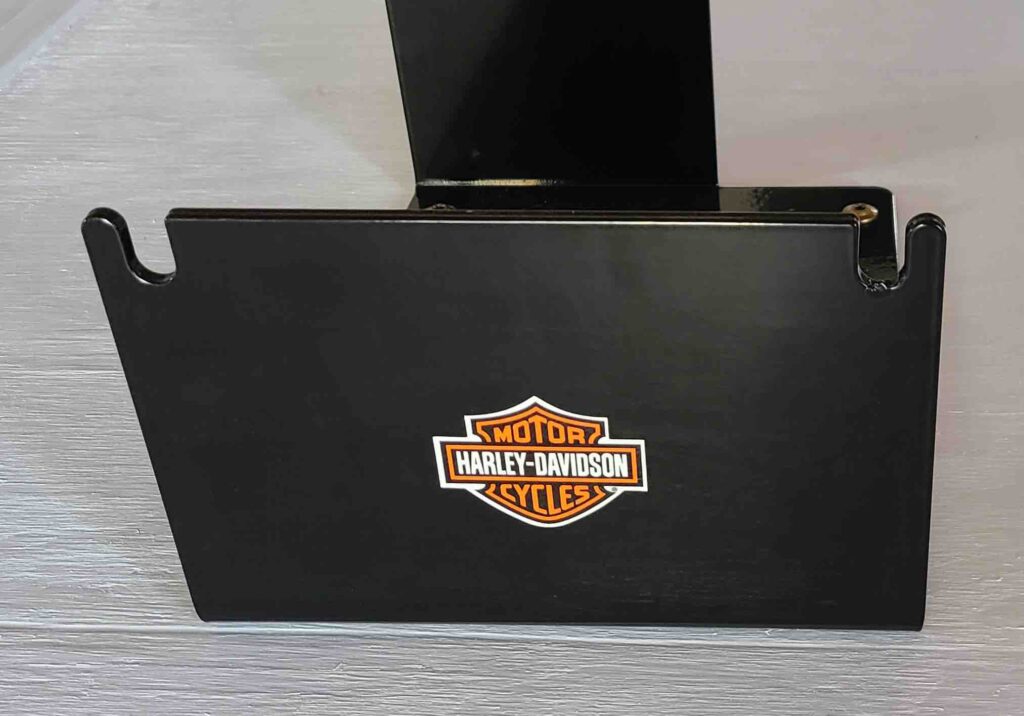
The workbench with engine stand is ready. The series of photographs below show the various stages of cutting and assembly. My thanks to Tiffany from dreamdesigndiy via Lumber Jocks (dreamdesigndiy, 2018) for the basic workbench idea. The posted photograph was actually an intermediate stage of a more complex build, but it served as an excellent launch point. I modified the design slightly to add cross-bracing into which the engine stand mounting screws could be driven. The added lip around the top surface is an attempt to foil Mr. Murphy whose famous law has a corollary – “A dropped tool will roll to the geometric center beneath the vehicle on which you are working.”

As noted in an earlier post, the project bench was made entirely from salvaged or leftover materials and hardware. I did buy some hardware for leveling the bench, but it turned out that a single shim at one corner solved the slight rocking motion, so I returned that hardware for a refund.

In the meantime, the parts manual (Harley-Davidson Motor Company, 2003) has arrived. It is a gold mine of diagrams and information. As stated on Page 1, it is not an assembly manual, but it sure helps to see how the parts are supposed to fit together and proper part names. Thanks to Shawn for the tip.

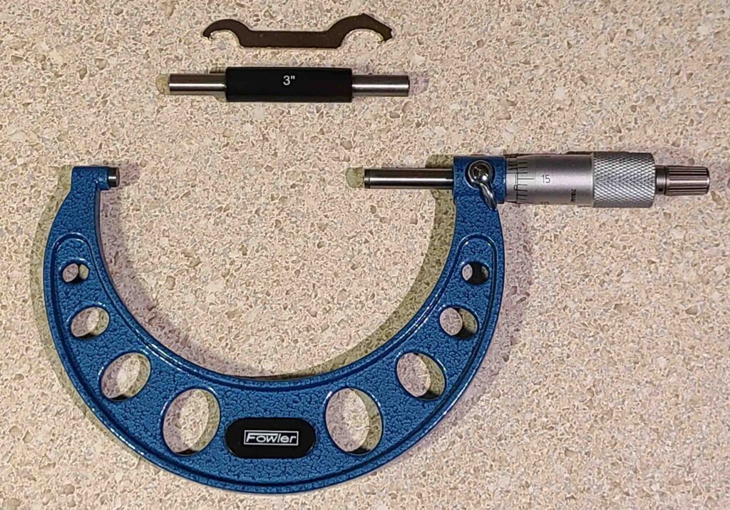
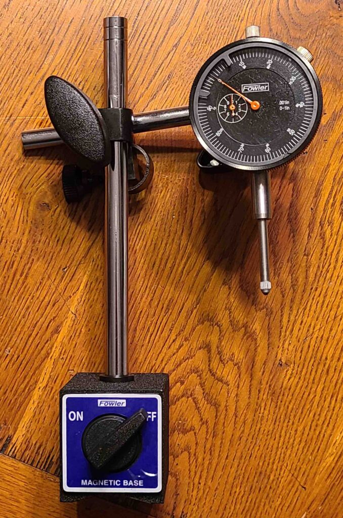
Some of the precision measuring tools have also arrived. The dial indicator, micrometer, and digital caliper are pictured below. I chose the 3-4 inch micrometer to measure pistons. There will probably be other things to measure outside of this range, but I will pick those up as needed.

The motorcycle is freshly washed and in the chock. I have removed the lower fairings and saddlebags to storage. The seat and battery are next. Then we dive into dis-assembly for engine removal. If I can resurrect my son’s old GoPro camera, then I’ll try to capture some interesting footage. Otherwise, it will be photos.

The Cost page lists purchases to date and the running total. I decided to charge the measuring tools to the project because I would not have bought them otherwise. Of course, I’ve always wanted the nicer calipers and such, but haven’t been able to justify the investment until now. While I wish that I could afford Mitutoyo, I believe the Fowler products will serve well.

Cheers!

Let’s Do The Math …

JMJ

In today’s post, we lay out the criteria for assigning costs to the engine rebuild project. Essentially, if I buy a part, tool, or manual for this job that I would not have purchased otherwise, then the cost is charged to the project. Incidental costs, like replacing a worn screwdriver, do not get assigned to the project because I would have needed to make that purchase anyway.

I expect the gray area will be tool purchases that have general use in the shop. For example, a large socket, a dial indicator, or a micrometer are all good things to have, and none are specific to this particular task. The question will be whether I would have bought the tool anyway, engine rebuild or not. If yes, then no charge.

The new manuals and the engine stand will be project costs, but not the original service manual. The cost of the domain and blog are not charged because neither are necessary for rebuilding an engine. The break-even cost will be the total dealer service quote for replacing the engine ($7,242.01) less the estimated labor in that quote ($1,500) leaving $5,742.01 as the cost to beat. We will keep track of expenses against this upper limit budget number. I am confident that we will have a running machine, a better collection of tools, and many useful new skills with budget to spare.

Speaking of manuals, both the Haynes (Editors of Haynes Manuals et al., 2014) and Clymer (Scott, 2005) manuals have arrived. I was up until midnight reading through the Haynes manual that arrived first. When the Clymer book showed up the next day, I was surprised to learn that Clymer is a division of Haynes. I will be very disappointed if I find that I have purchased the same manual under different names. When I searched the web for differences between the two, I landed right in the middle of a 3-way philosophical and religious battle between folks advocating for Haynes, Clymer, or the manufacturer’s service manual (or any combination of the three). I have all three and will consult all three. If any worthy opinions or glaring differences emerge, I will share in a post. Otherwise, I am slowly backing out of the room.

The garage bay is almost ready. I want to add some more lighting, but that can wait for a while. I have scrounged enough material to build the workbench to which the engine stand will be mounted. I told my wife and myself that all that crap, ahem, extra building material, would come in handy some day. Today is that day. I plan a working surface of 30” x 48” at a height of 32 inches.

I hope everyone is having a worthy Holy Week leading up to a blessed Easter.

Howard

Quote of the day: “There is a work around for every ‘special tool’ requirement.” (djl, 2011)

First things first

JMJ

Welcome! Now that the website is up and running, it’s time to write. In this post, we set the stage for the project. As explained on the Why we’re here… page, I’ve got a broken motorcycle, and I’m going to rebuild the engine. This blog is intended to chronicle the journey in words and photographs.

I have already started searching for applicable videos on YouTube to get a sense of what might be involved. So far, two channels have captured my attention, Budget Rebuilds (Budget Rebuilds, n.d.) and Subi-Performance (Subi-Performance, n.d.), for different reasons. I am sure there will be others.

The Budget Rebuilds 7-part series Blown Up Harley Engine? Can We Fix It? seemed to fit our situation and was inspirational on several levels. I liked the way the host jumped right in on his project. His confidence, based on extensive experience, is contagious. The initial work with the engine on the bench (Budget Rebuilds, 2020a, 7:22) with scrap wood support was a bit scary, but in the next segment (Budget Rebuilds, 2020b) he had picked up an engine stand. It obviously made a huge difference, so I ordered one for our project. There were more than a few nuggets of wisdom in the comments.

The Subi-Performance channel is amazing. I have never seen a shop so incredibly clean, organized, and well-lighted. Everything they do is measured and torqued to specification. This is the space I aspire to create for this project. I also like the project tables and wire racks they use to keep parts organized. The plan is to build a project table on which to mount the engine stand for 360-degree access to the engine. I’ve got a lot of cleaning to do.

A service manual from the manufacturer is usually among the first things I purchase whenever a new vehicle joins the family. This motorcycle was no exception, so that resource is already in hand (2004 Harley – Davidson Service Manual – Touring Models – P/N99483-04 (2004 Touring 1450-Cc 5-Speed Models), 2003). Several other manuals (Clymer and Haynes) are on the way to provide comparison of process and to get ideas for workarounds where needed.

I also ordered, and have already received, the Harley-Davidson Twin Cam Hop-Up & Rebuild Manual by Timothy Remus (Remus, 2017). It really helps to see quality photographs of parts I can expect to encounter in the tear-down and rebuild. The discussion in Chapter Two, Twin Cam History, about spring loaded cam chain tensioners (Remus, 2017, p. 19) has given me an item to watch for early on in the tear-down, starting with draining the oil. I plan to start with a sparkling clean oil drain pan and to strain the oil for evidence of tensioner pad disintegration and other foreign matter.

So, we begin.

  • Clean and organize the work area,
  • Research the procedures, and
  • Build the project table.

Cheers,

Howard