Bearing Up!

JMJ

Greetings and welcome!

In our last episode (September 2022 for cryin’ out loud), most everything was here or on its way. It seemed that rebuilding was about to begin. One major item that had yet to arrive was the Crankcase Bearing Remover and Installer (JIMS #1672). The thinking here was that we might as well put in new bearings while we have the engine in pieces. I ordered one shortly before the September blog post. Soon after the post, I learned that this tool would be delayed. After searching other sources, all of which were out of stock, I resigned myself to wait.

And wait. And wait. In fact, after three separate extensions (read “delays”), I contacted JIMS directly to learn that a new production run of this tool would be scheduled at some point, but no dates. When the fourth delay notice arrived, I decided to take a different approach.

Using my fancy new electronic caliper, I took measurements of bearings and crankcases to design my own tool. The concept was pretty clear. With plans in hand (thanks to a Mechanical Drawing class that I took as a freshman), I went to my local machine shop. Following a brief discussion with the owner, it looked like I would be waiting as long or longer for my custom tool because of the incredible backlog of work. That was disappointing.

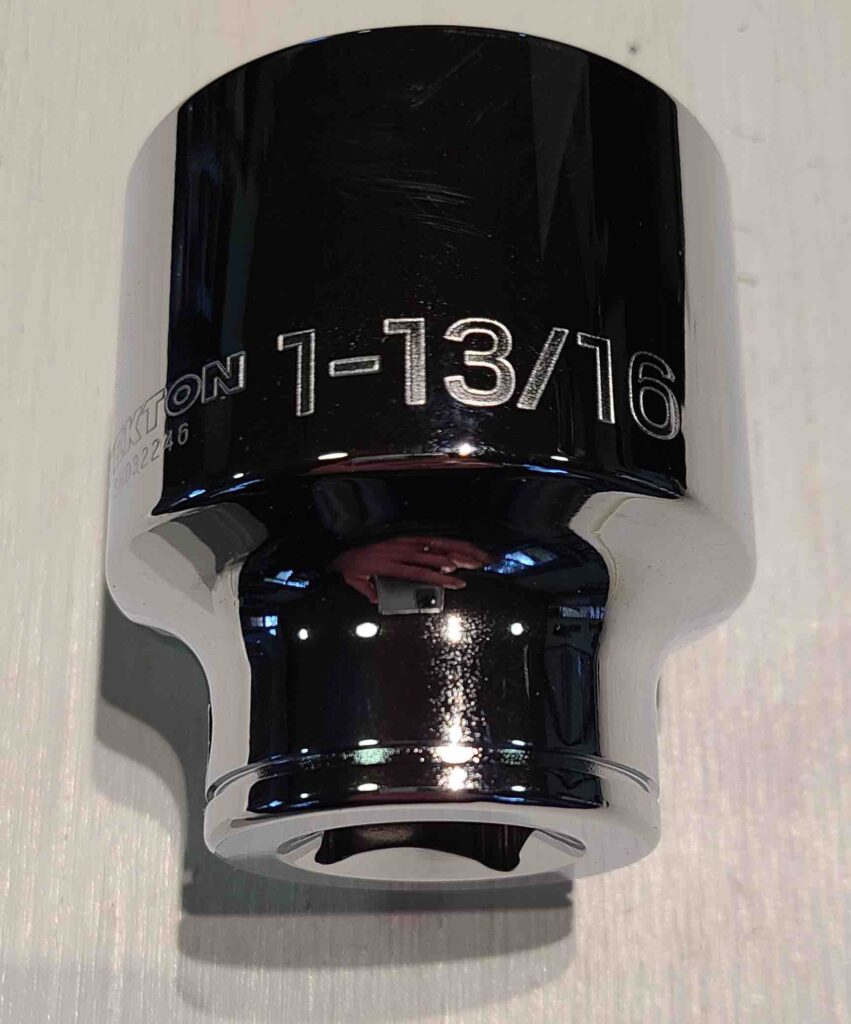
As the concept marinated in my imagination, it occurred to me that there were bound to be other combinations of supports and drivers that would allow me to swap these bearings. Reviewing the measurements, I concluded that a piece of 3-inch pipe and a 1-13/16-inch socket would get the job done. It all came together on November 1, 2022.
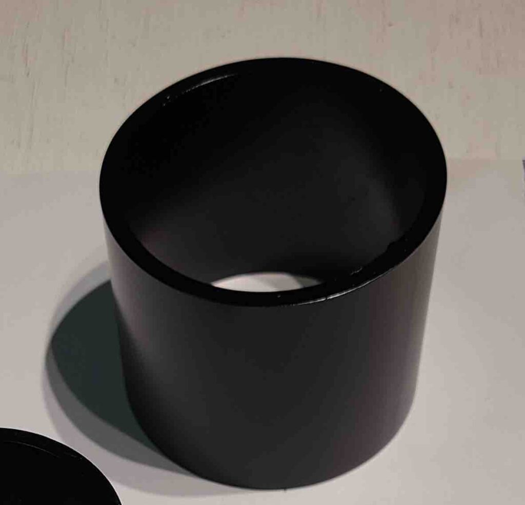
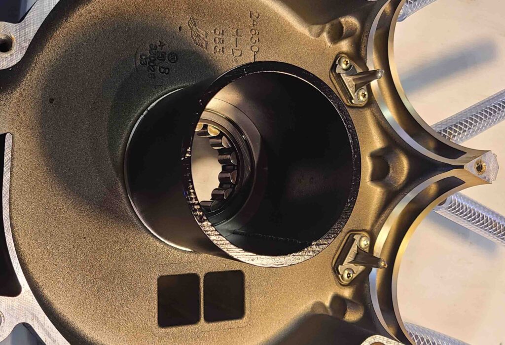
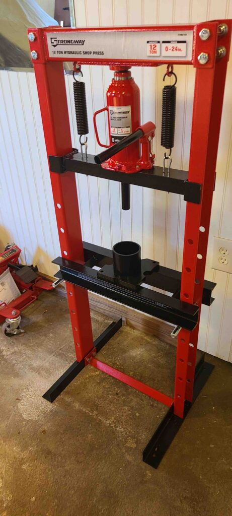
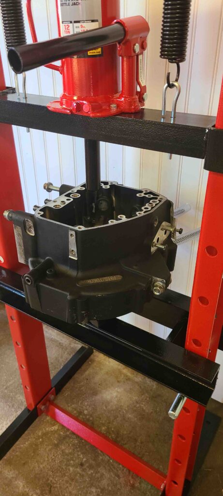
Here’s the stack-up. One section of 3-inch pipe that was three inches long on the bolster plates of the hydraulic press.
Left Crankcase Half positioned over the pipe.
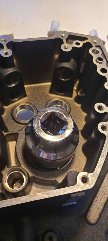
1-13/16-inch socket on the bearing. I also put a washer (not shown in the photo) on top of the socket to engage the ram.
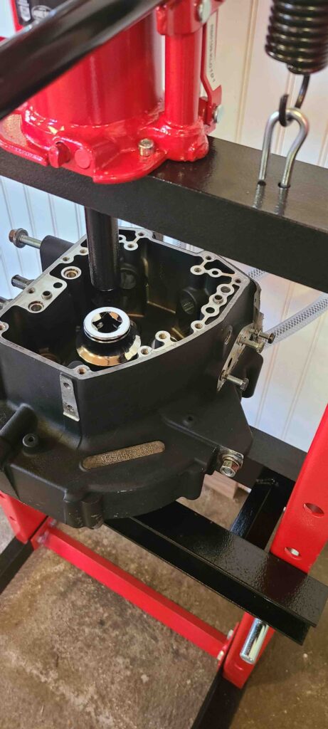
And then we pressed.

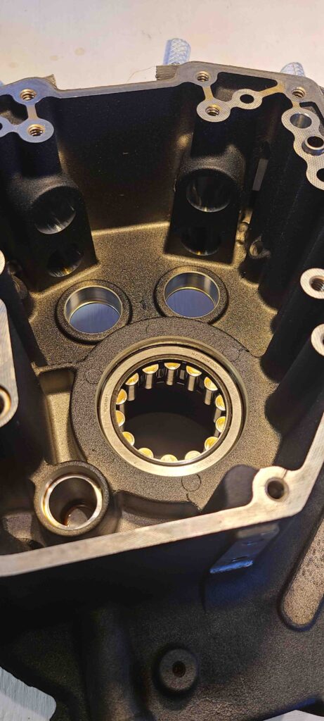
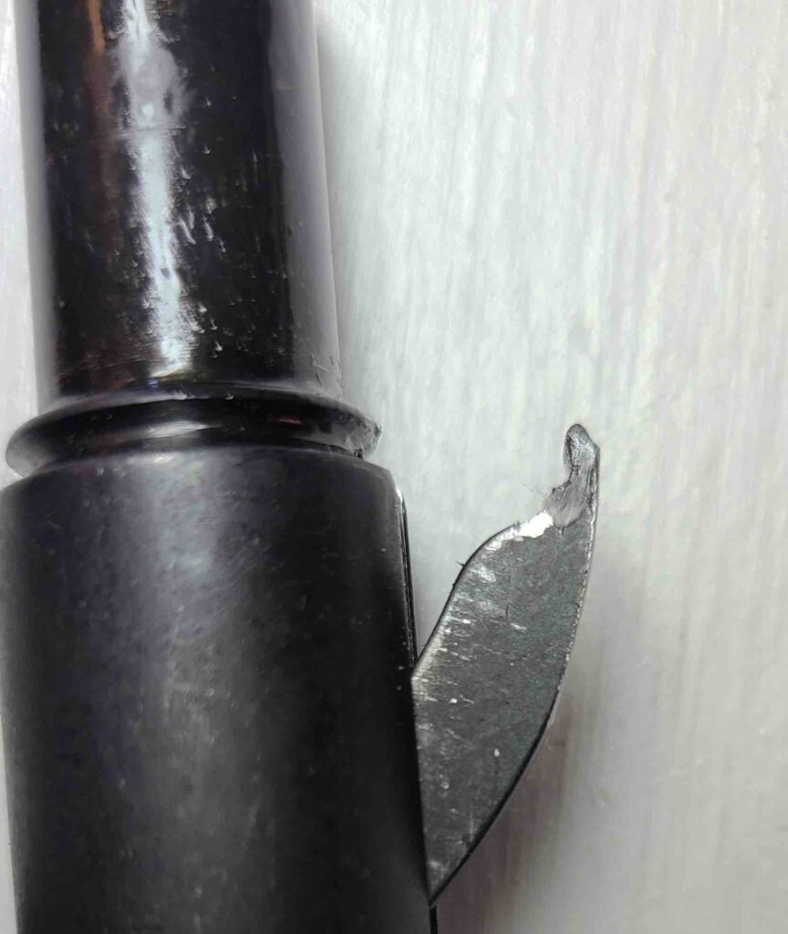
I was pretty pleased with the results until I examined the crankcase half. As seen in the photos below, the final release of the bearing caused a fracture on the lip of the case.
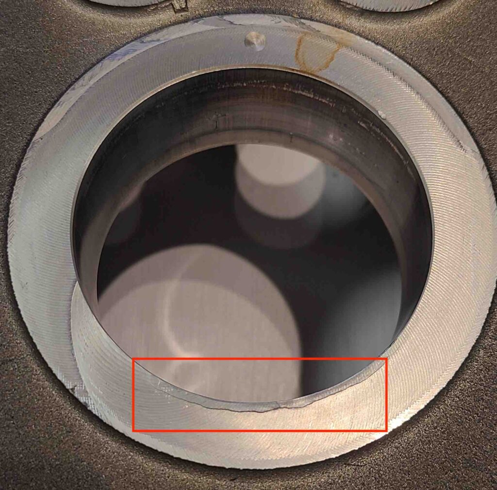
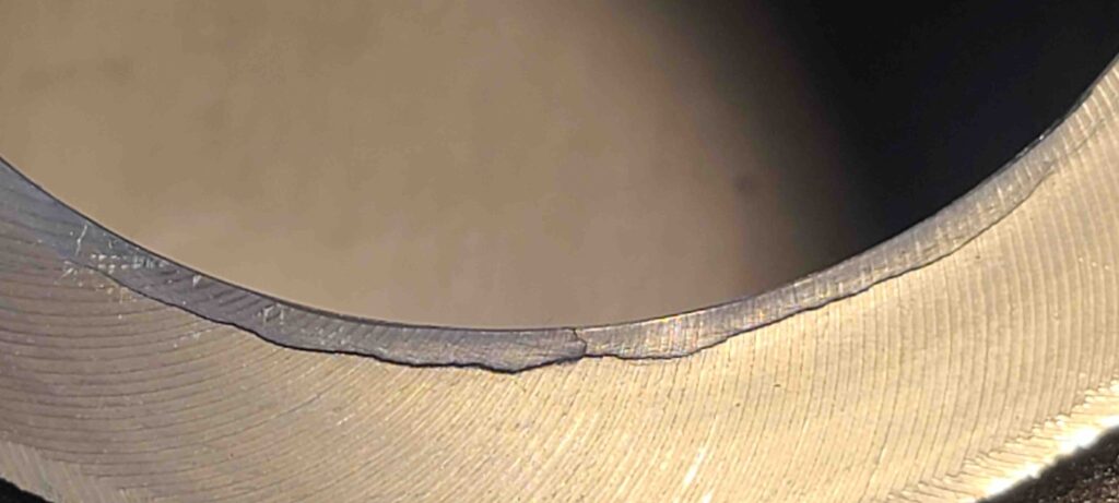
After putting the tools away, I went inside to sulk, convinced I was now looking at buying a new crankcase.

A new crankcase (sold as a mated pair) listed for $1,570 – plenty of motivation to find a solution. Taking measurements of the damaged area on the surface, it looked like the damage might be removed while leaving the entire surface area for the bearing’s outer casing. Back to the machine shop.

Fortunately, the owner of the machine shop was an old Harley guy and understood exactly what I wanted when I asked him to mill out the damage leaving a slight bevel. We didn’t know if the fracture went deeper into the casing, but he was willing to try. After some waiting (backlogged work), I got the call in February 2023 that the crankcase was ready. The results were excellent.
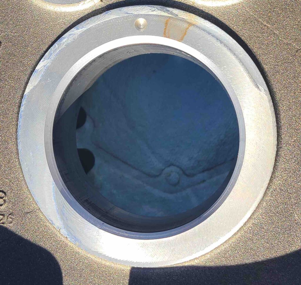
The larger problem of installing the new bearing in the Left Crankcase Half and then dealing with the Right Crankcase Half was still a problem, but things were looking positive again.

I have met people who refuse to wear brand merchandise (e.g., hats, jackets, shirts, etc.) to avoid giving Harley-Davidson free advertising. This always struck me as odd, but it’s a free country. When I see someone in HD apparel, I use it as an opportunity to open a conversation about motorcycling, in general, and Harleys, in particular. This is exactly what happened when I met an electrician at a job site wearing a hat. One thing led to another and suddenly I had a name and number for a shop that could take care of the bearing swap. Thank you, Lord, for throwing me a clue and introducing Antonio.

To wrap this up, we now have new bearings installed in both crankcase halves and are ready to begin reassembly.
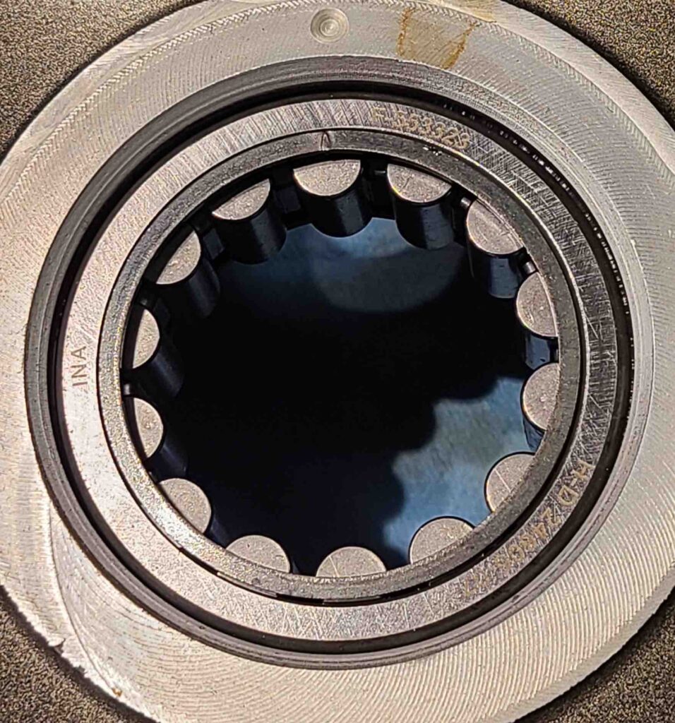
Best wishes and don’t forget to feed the seagulls!

Stuff’s coming in…

JMJ

Greetings! Welcome back to the shop! Just a few updates as we prepare to begin rebuilding.

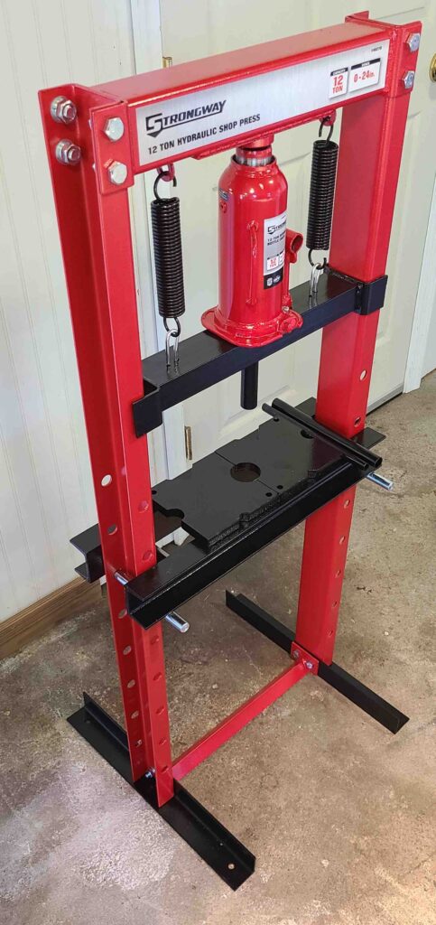
Looking ahead to some of the bearing work, I bought a small press at Northern Tool. It was on sale in the weekly flyer, and then I got another $30 off when I went to pick it up at the local store.

Strongway 12-ton Shop Press

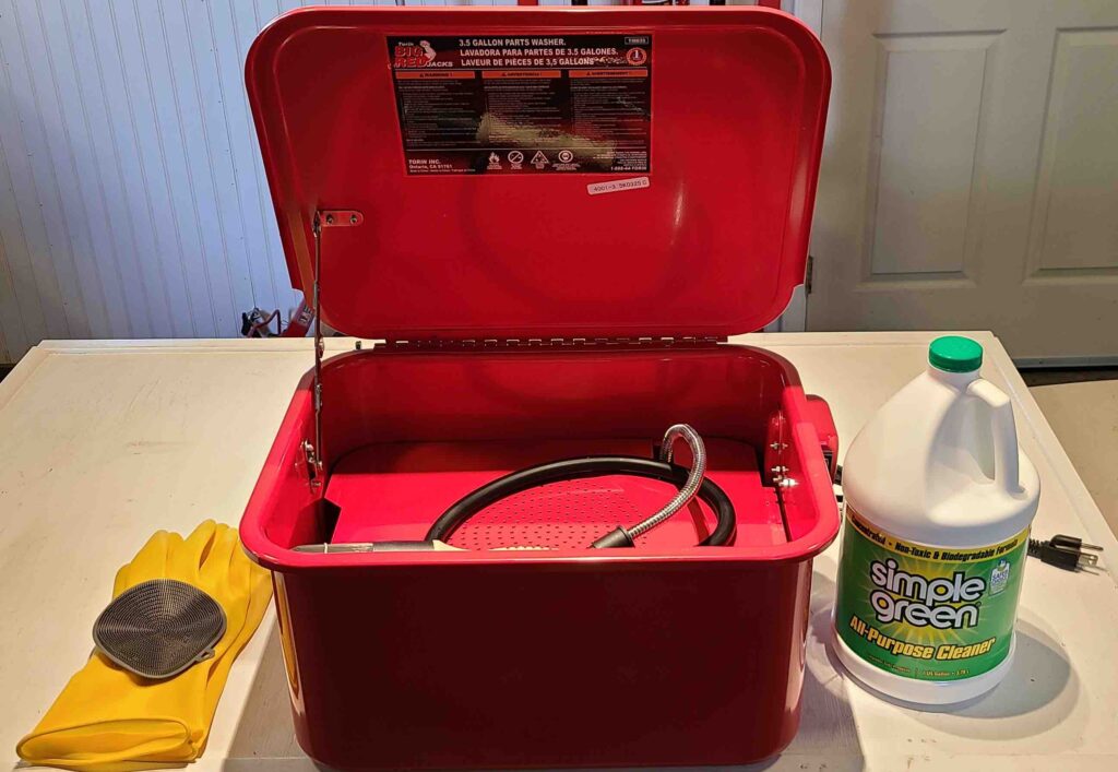
I also found a good deal on a parts washer, so I ordered one of those as well (amazon.com). The variety of water-based cleaning agents is impressive, so I selected a brand that promised to be environmentally friendly. As it turned out, that product can discolor raw aluminum, so I promptly returned it. (Moral here is to read the small print carefully.) My son recommended Simple Green based on his experience with parts washers and people he knows, so I bought a gallon at the local Walmart.

Torin Big Red Parts Washer with Simple Green

Recently, I tripped over fixmyhog.com. The recommended video happened to be about installing gear-driven cams. I watched the entire series in one sitting. Then I watched it again. See links on Resources page. With the clarity that came from watching Mike Roen install that kit, I decided this was what I wanted to do on my machine. So, I ordered the Cam Chest Conversion Kit, Gear-Driven, with .510″ lifters from S & S Cycles. This is the most lift recommended using stock valve springs.

At the same time, I ordered the new flywheel. Since I’m not looking to increase bore or stroke, nor do I wish to make major modifications to the crankcase, I decided to stick with stock roller bearings in the mains. Another factor against the Timken bearings was the $1,500 installation kit. Yikes! Not for a one-time use tool. I’m sure that I could have found someone to do that install for me, but, I’m trying to do as much as I can in my shop. With the new S & S flywheel assembly, I am now officially over budget. Technically, I probably could still be under budget had I stuck with chain-driven cams and the original lifters, pushrods, etc., but this engine should be bullet-proof when we’re done. A short “unboxing” video follows.

Unboxing flywheel and cam kit

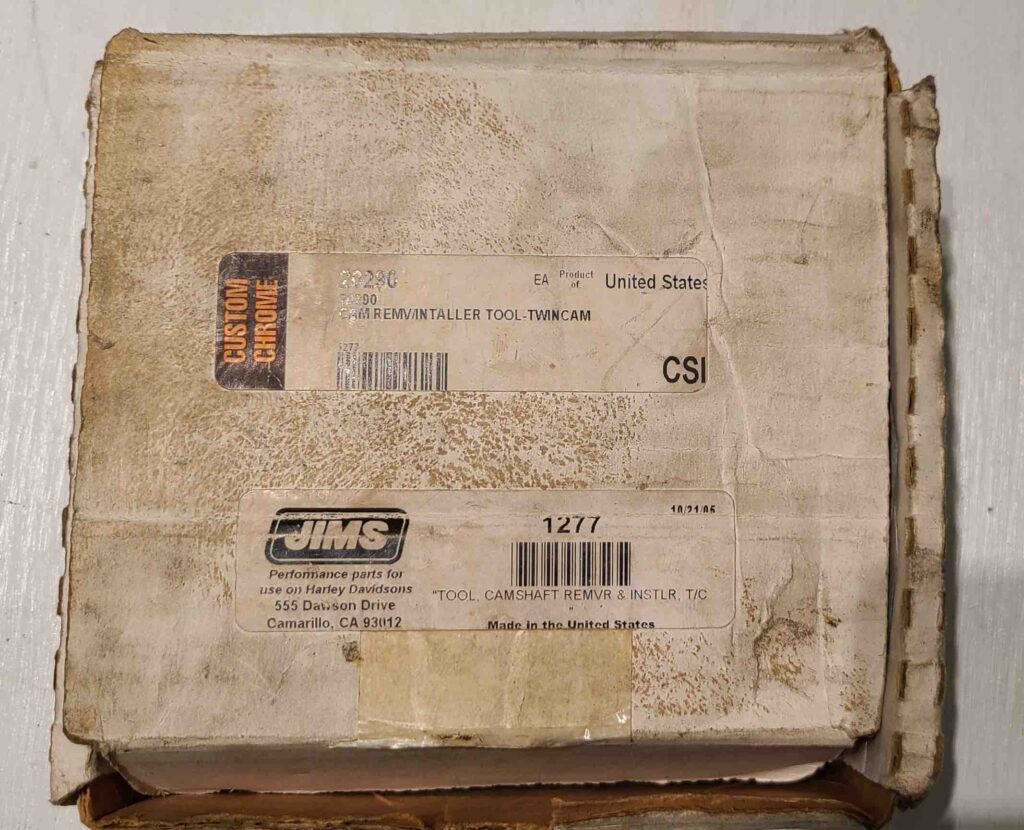
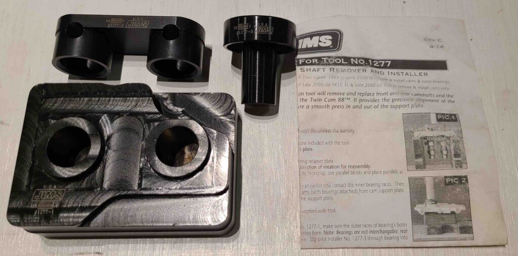
The Camshaft Remover – Installer (JIMS 1277) has also arrived. This one came new from ebay.com. The box wasn’t too pretty, but the parts were still sealed in the original plastic and were in great shape.

Camshaft Remover – Installer

That’s about it for now. More soon!

Cheers!

Splitting the Crankcase

JMJ

Greetings, ya’ll! Welcome back! Just a short post today to get caught up.

The last major step in disassembly was splitting the crankcase. The short video below shows the action.

Splitting the crankcase

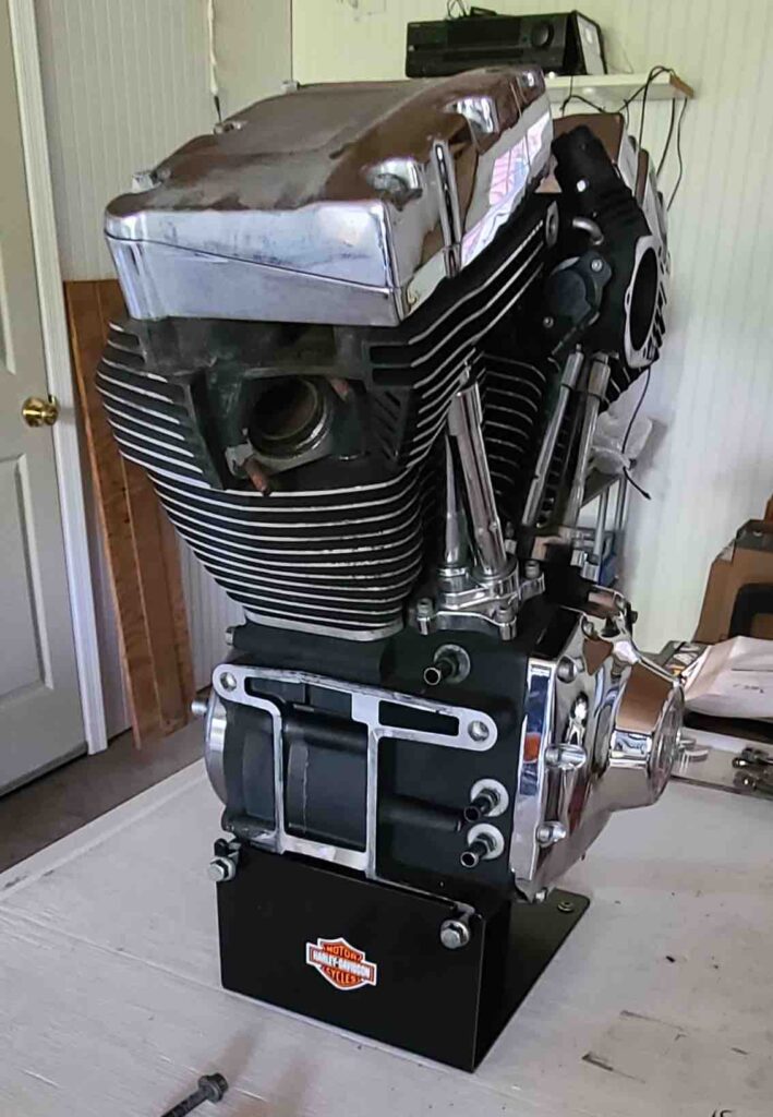
It was a odd to see all the major parts on the bench with nothing left on the engine stand.

The first contact with a machine shop confirmed what I suspected. The flywheel assembly with a damaged shaft is essentially scrap metal. After a bit of sticker shock, I have resigned myself to buying a new, balanced, welded flywheel assembly and a complete gear-driven cam kit, including a new support plate and oil pump. I do plan to disassemble the old oil pump to see what damage the tensioner pad may have caused, but that will be mostly out of curiosity. The upshot here is that I may be over budget with these upgrades, but I should end up with a sturdier engine.

In other news, the torque plates and cam bearing tools have arrived. More information on the Resources page. We’ll get the cylinders and heads prepared and take some measurements. Hopefully, we’ll be able to reuse all of the top-end components.

Cheers!

Howard

Cam Chain and Support Plate

JMJ

Greetings! Welcome back to the shop! Today, we get to the heart of the matter.

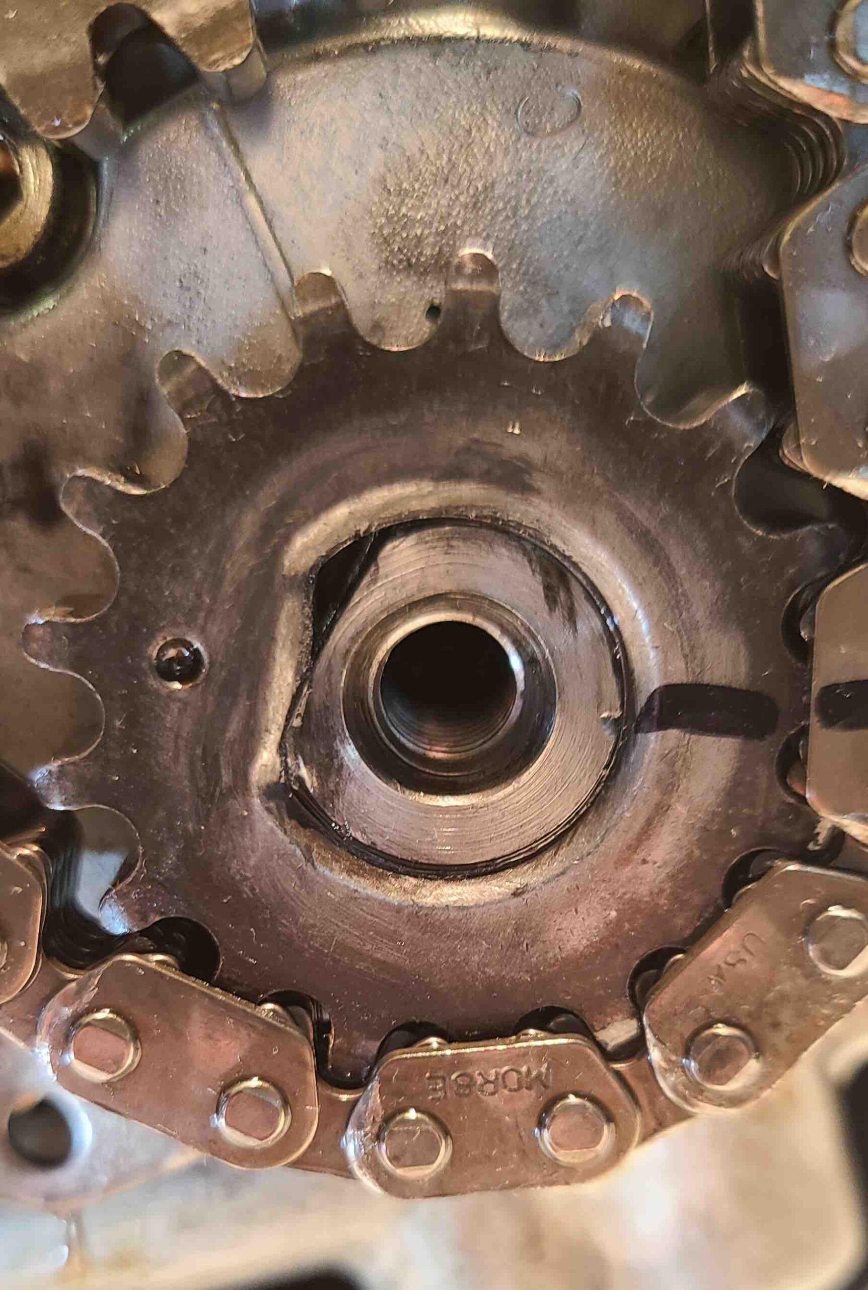
Having previously removed the cam cover, we got a first look into the crankcase. Now we tackle the cam chain. I started with the assumption that I would be reusing many of the components (sprockets, etc.). A major issue emerged shortly into the disassembly.

Cam Chain Removal

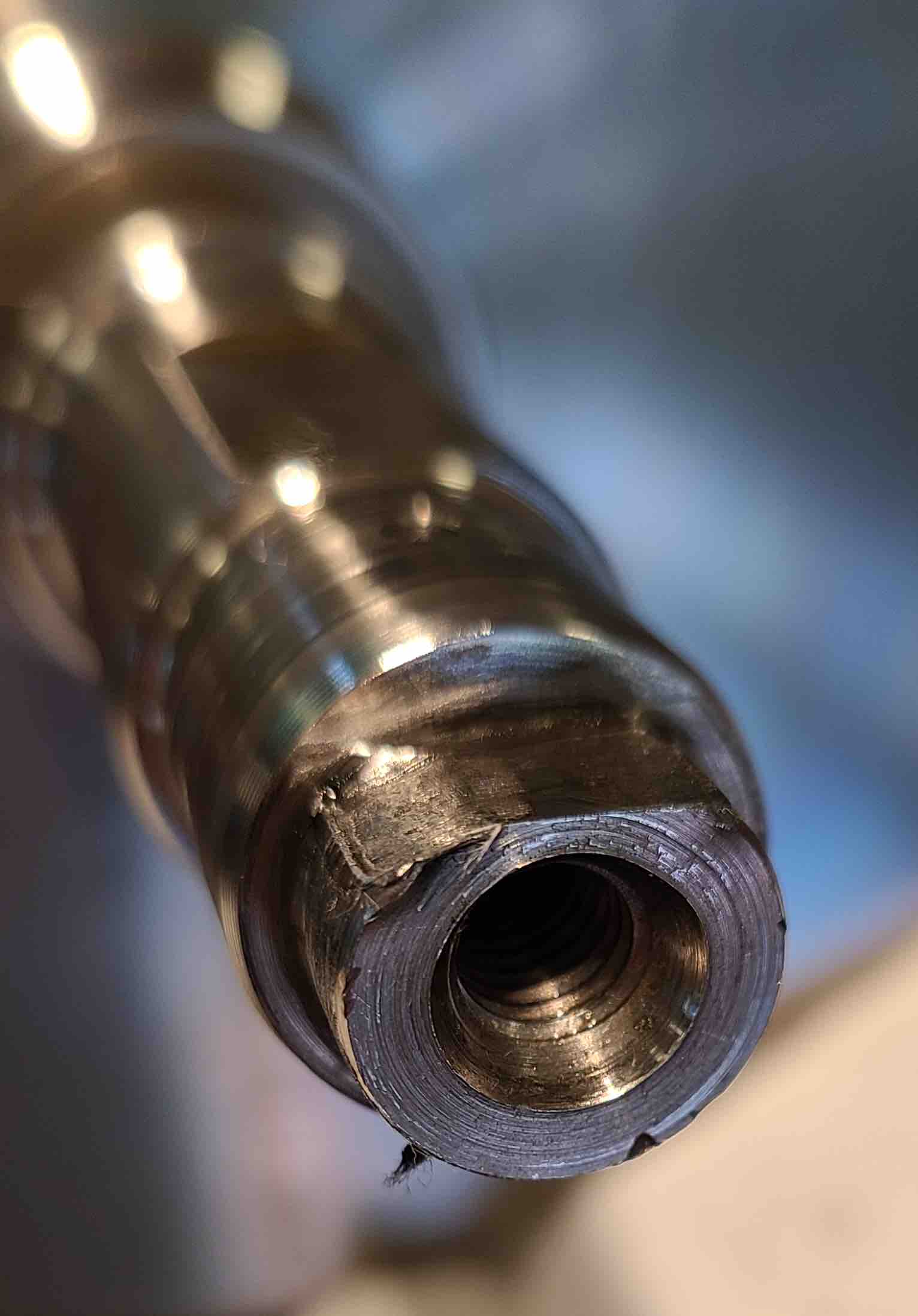
The net result of this procedure is serious concern about every single component, especially the crankshaft. I plan to talk to a machine shop about what repair might be possible.

With the cam chain out of the way, the cam support plate is ready to go.

Cam Support Plate Removal

Next step is to split the crankcase. In the meantime, I need to start pricing parts to inform the decisions that I will have to make in the near future. I also need to sort out how to effectively clean parts to ensure that no flecks of tensioner pad foul an oil channel and cause another failure in the future. A lot to think about.

In the meantime, a few new tools arrived. One is a larger micrometer (4-5 inch) with an anvil adapter set that will allow us to measure the pistons. Another is a small micrometer (0-1 inch) with a small bore gauge set for measuring bushings and rocker arm components. I also picked up a bore gauge to measure cylinders. Just need the torque plates to properly mount the various components for measurement. I love quality tools!
Cheers

Pulling the Alternator Rotor

JMJ

Greetings! Welcome back!
So, the alternator rotor has been patiently waiting for its turn and that day has finally come. Actually, that day was closer to the first of August, but we’ll pretend. Since I could not find the Harley-Davidson Alternator Rotor Remover/Installer (at least not a complete unit), and the JIMS alternative was unavailable until October, I kept searching for an alternative tool. Patience is sometimes rewarded. Jireh Cycles in Arnold, Missouri, carries such a tool from Ultima (see Resources). After doing a quick fitup with no instructions (that was odd), I pulled the rotor as you can see in the short clip below.

Alternator Rotor Removal

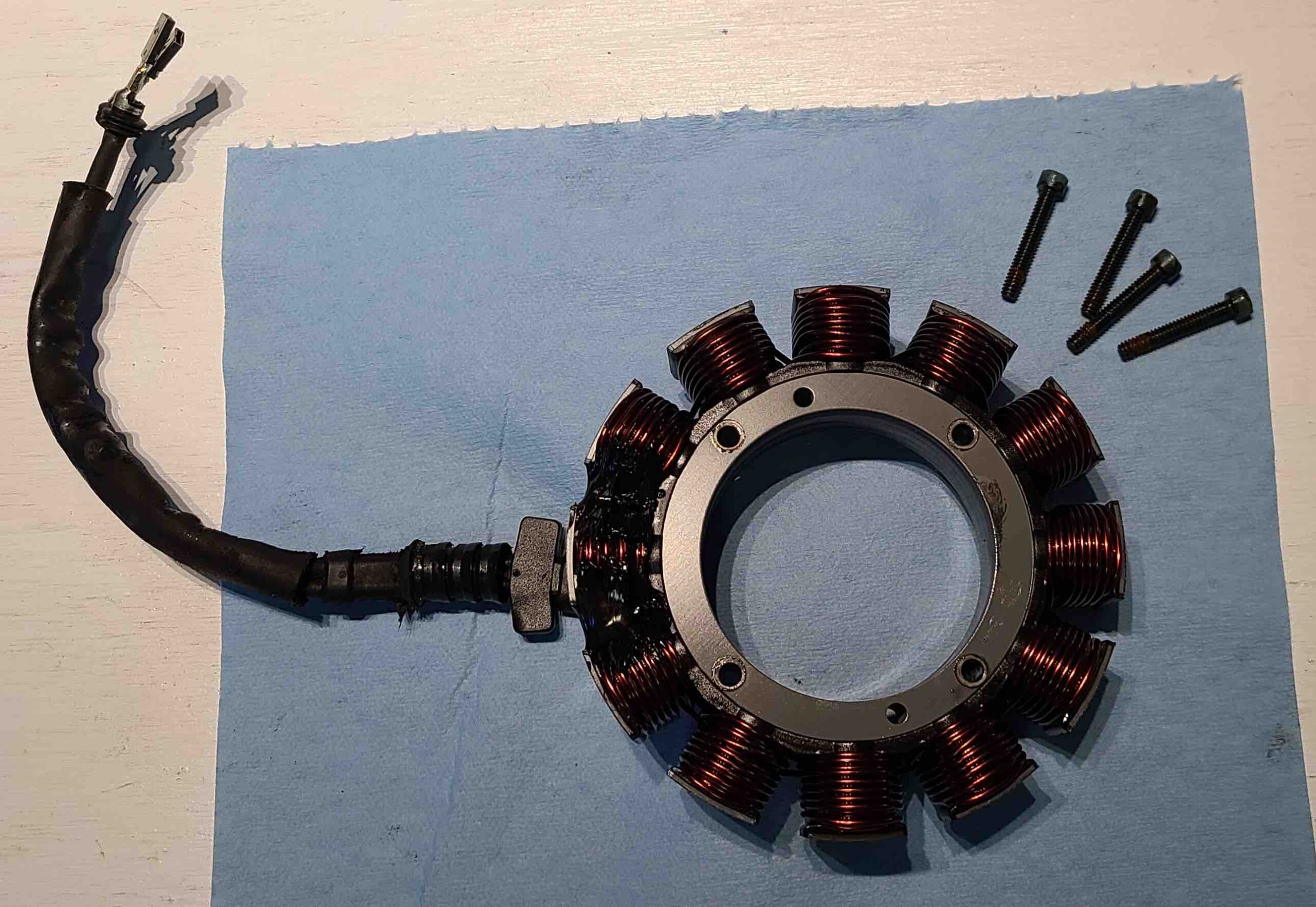
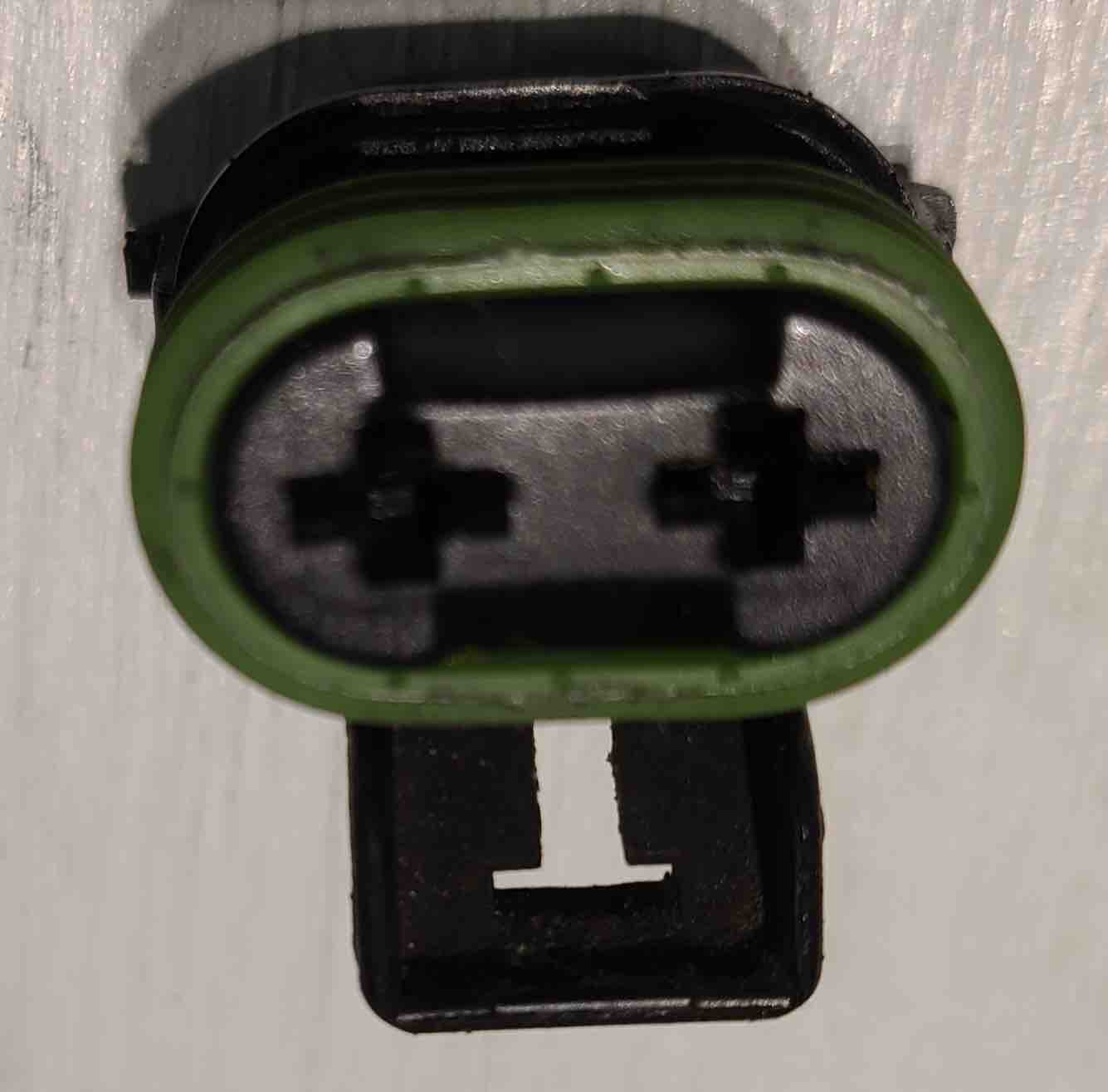
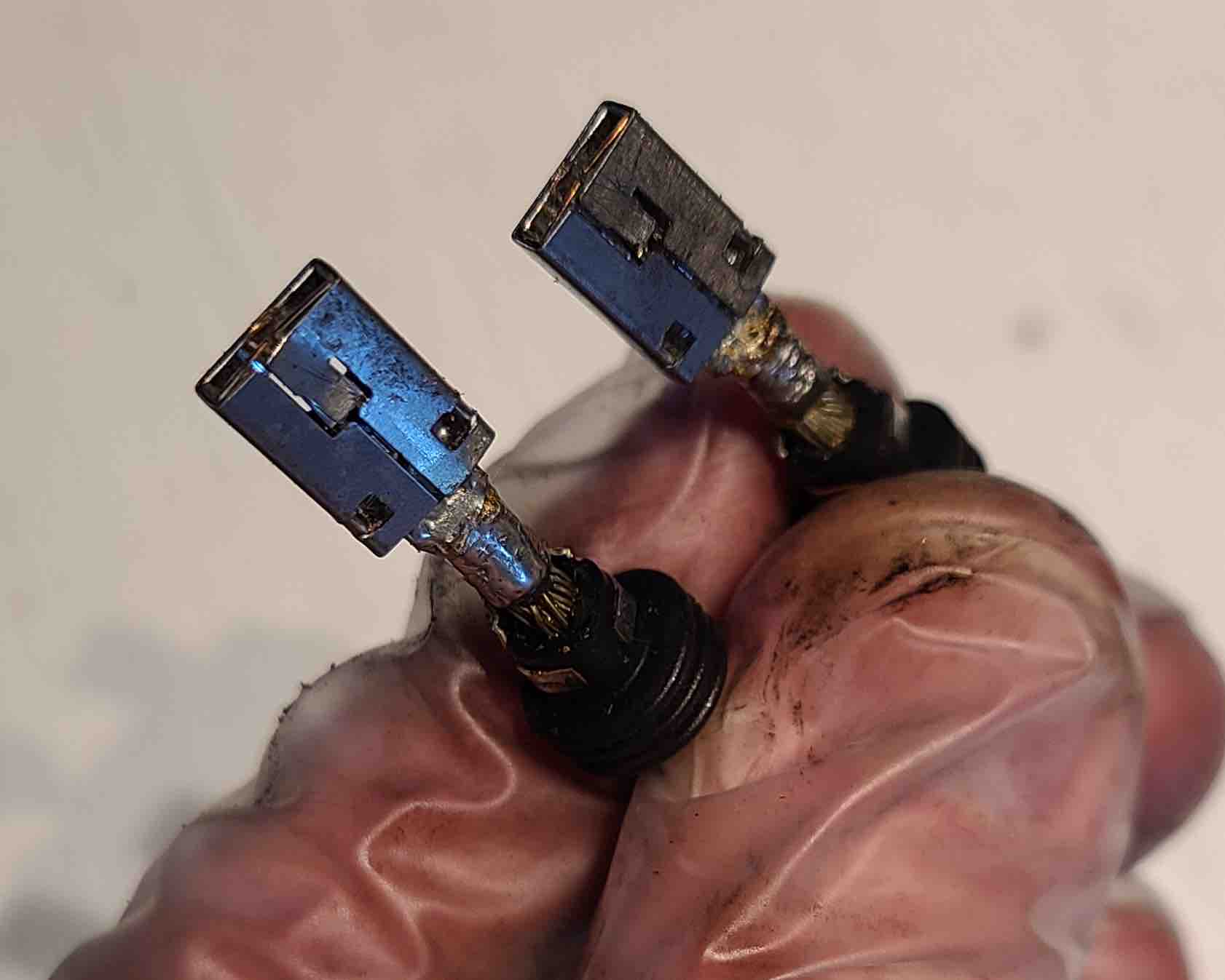
The final step was to remove the leads from the stator cable plug and pull the stator. Photos below.

Next, we’ll be removing the cam support plate.

Cheers!

First Look in the Crankcase

JMJ

Greetings! Welcome back to the shop!

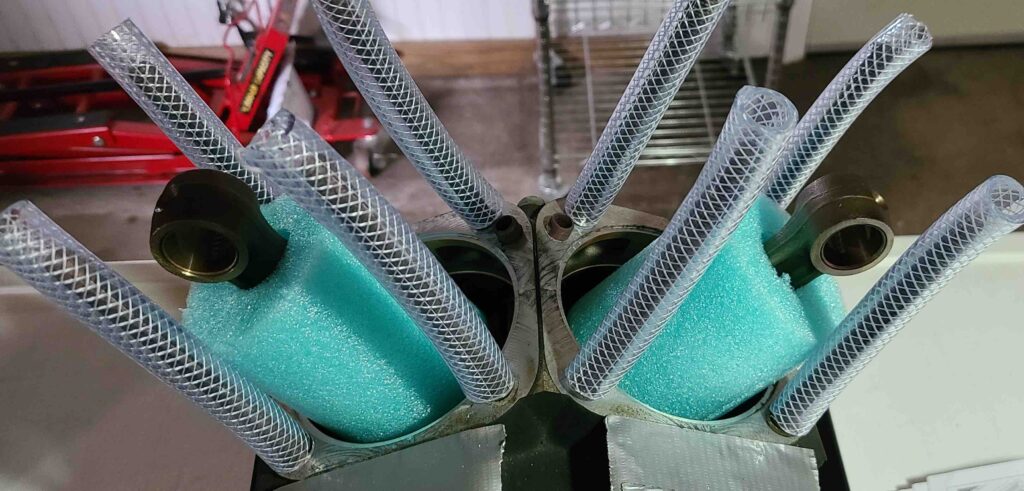
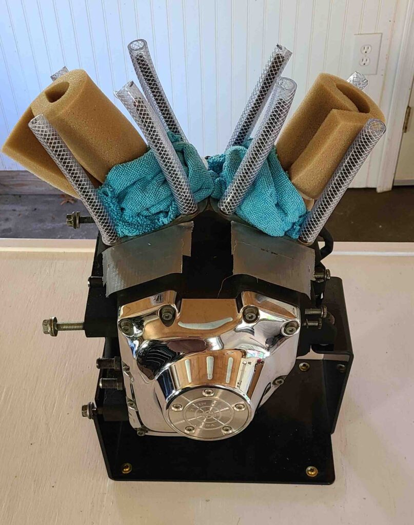
Today was a cleanup day. I spent some time getting tools back to their proper drawers, mounting a new shelf, and puttering in general. I changed out the foam sheet wrapping the connecting rods with a short section of pool noodle. A perfect fit for about a buck. Since I only needed about 6 inches and the rest will go to the grandsons, I’m not charging the project for the noodle. The actual time on the engine was short, but highly entertaining. I hope you enjoy.

Pool noodle protection

Reading ahead into the Bottom End Disassembly section of the service manual, I was concerned about acquiring a Cam Chain Tensioner tool to get started on the teardown. As it turned out, I can wait on that tool for a bit.

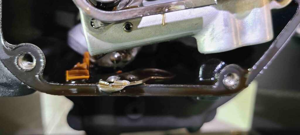
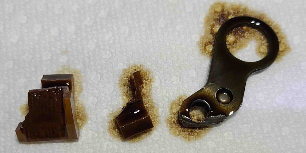
Once the cover came off, the main problem was fairly obvious.

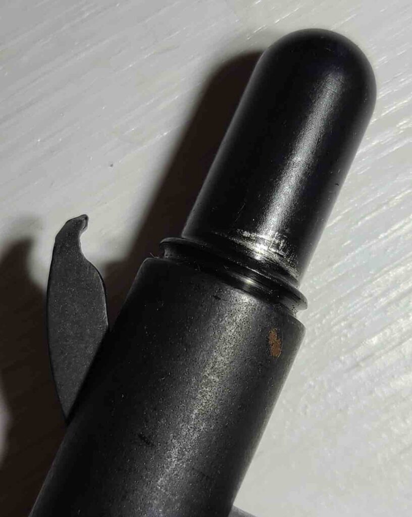
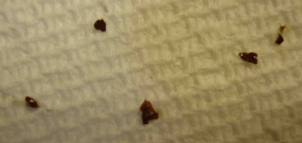
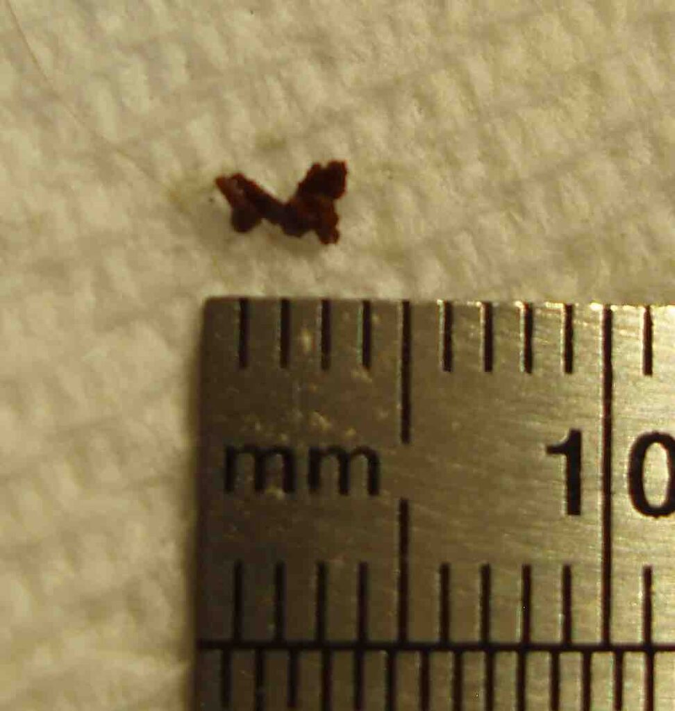
Tensioner pieces in bottom of crankcase
Tensioner pieces
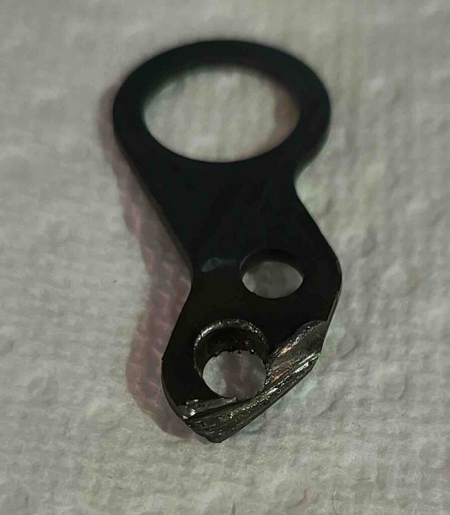
Wear on metal

I suspect that the metal shavings we saw on the oil plug during the initial draining may have come from this part.

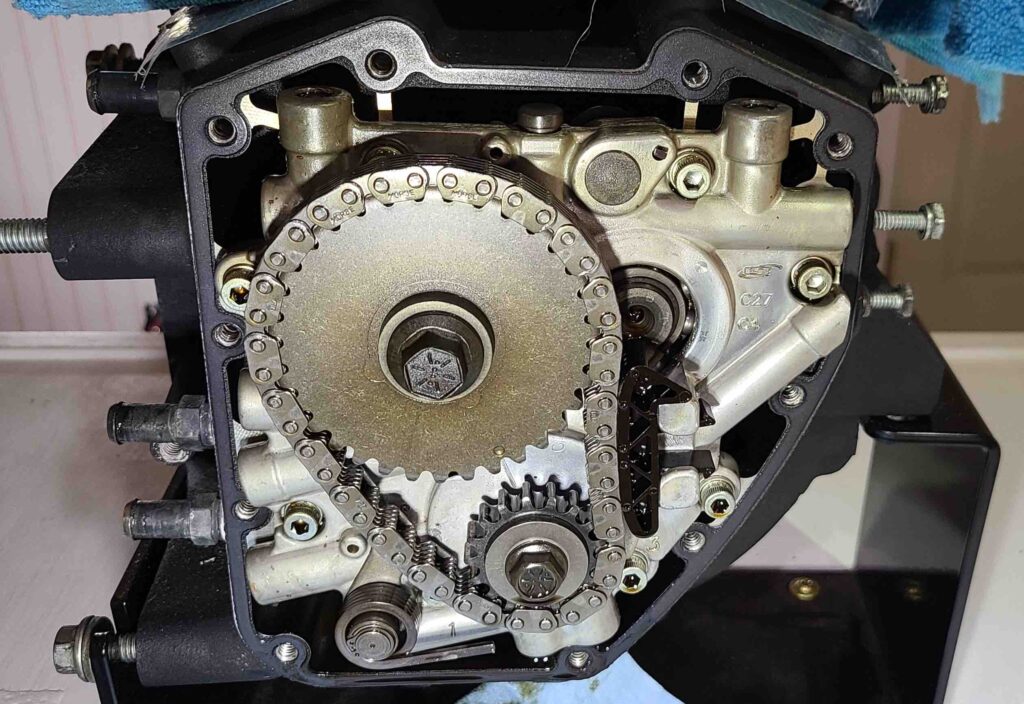
View of cam chain

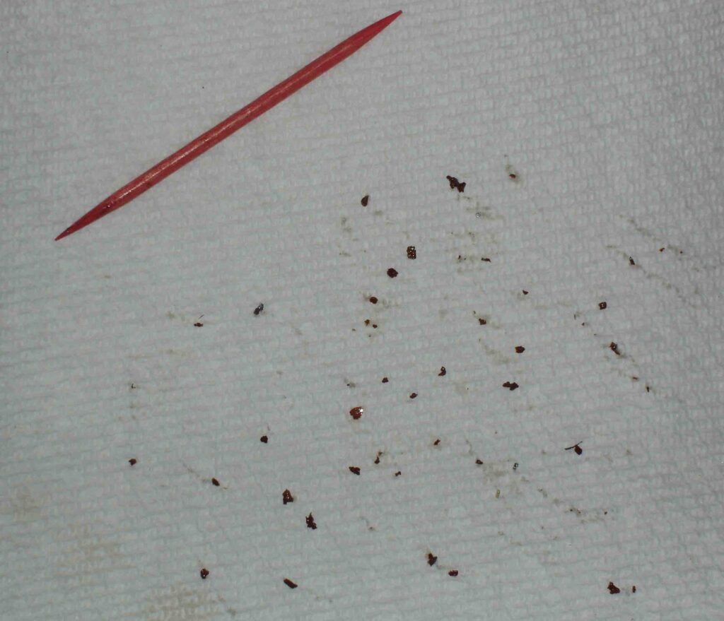
Seeing the size of the debris, I think that this part failure could have been a lot worse. The cursory inspection of the sprockets and chain revealed no obvious damage. The orange flecks that we found in the oil, the oil pan, and the oil filter were strewn about the crankcase as well.

In hindsight, I probably could have started this whole process by removing the cam cover to verify the original suspicion. Full credit to the Remus manual (Remus, 2017) for this tip — they nailed it.

We’ll soon get started on the rest of the teardown for a thorough cleaning. Then we can start measuring parts for wear and planning the reassembly. Who knows? I might even get a ride in this season.

Cheers,

Howard

Top End Disassembly Complete

JMJ

Greetings! Welcome back! I’m trying to get better at posting smaller segments more frequently, so I spent a day or two sorting through photographs and video to get the story together. Here it is for your reading pleasure.

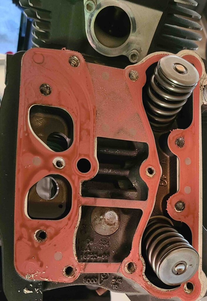
Picking things up from the last post (rocker box removal), the last stage in top end disassembly is removing the cylinder heads and cylinders. Starting from the gasket that one of the rocker boxes left on the cylinder head, we loosened the cylinder head bolts and removed the cylinders. As you will see in the video, there were a few minor surprises along the way.

Rocker box to cylinder head gasket
Cylinder removal

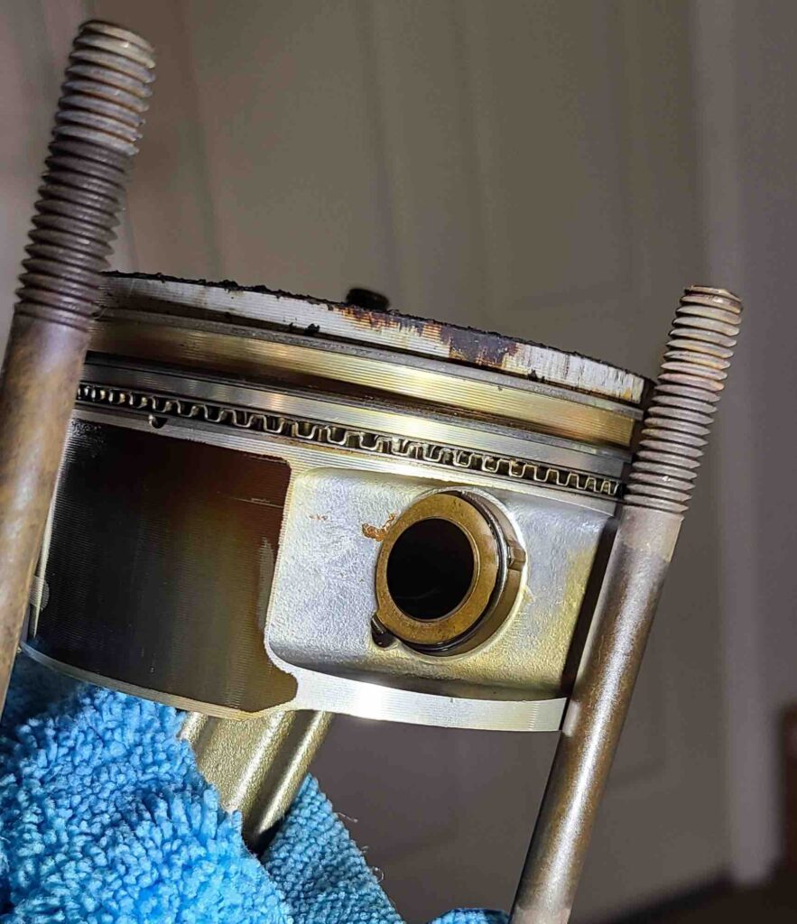
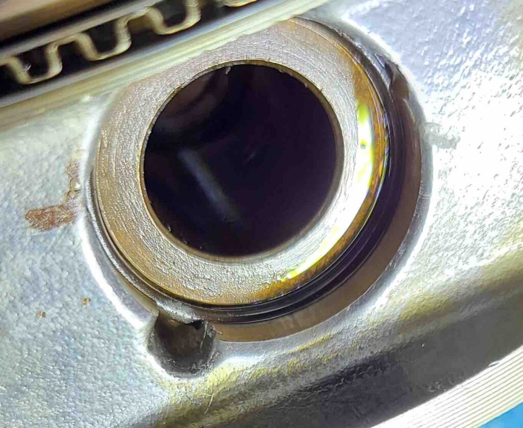
After removing the cylinders, the next step was to detach the pistons from the connecting rods. This requires extracting a circlip (piston pin retainer) from one end of the wrist pin (piston pin) and then pulling the wrist pin to free the piston. Each step requires a tool and we had both tools.

Extracting the circlips proved to be a bit tricky. The special tool essentially seats inside the wrist pin and a small claw compresses the circlip in its locking groove so it can then be pulled out. The tool was just a bit too large to engage the circlip, so I called the vendor and then the manufacturer. A big shout out to George at George’s Garage (https://www.georges-garage.com) and to Megan and Bob at Rotech, Inc. (search Rotech in Mayville, WI on facebook). With their guidance and a bit of judicious filing, the tool did exactly what it was supposed to do. Thank you!

With the circlips removed, the wrist pins were easy (with the special tool).

Pulling wrist pins and removing pistons

Finally, we wrapped both connecting rods with some sheet foam to keep them from banging against the edge of the crankcase where the cylinder seats.

Wrapped connecting rods

Next, we dive into the bottom end disassembly.

Cheers,

Howard

Rocker Boxes Removed

JMJ

Greetings! Welcome back to the shop. We’ve made some progress on the engine, the shop, and tools since the last post, so here are the details.

The shop is now closed to the elements. Looking ahead to the day we reassemble the engine, it will help to be able to thoroughly clean the space and minimize foreign material that might foul close-tolerance parts. The garage bay opening now has French doors and two barn windows to provide as much natural light as possible. The French doors both function to create an opening large enough to get the motorcycle out of the shop when that time comes. One small removable panel provides a hole large enough to stage a shop fan to get some air moving – an important consideration until other arrangements can be made (e.g., air conditioner). The next shop improvement will be a dehumidifier. Ours is not a dry heat.

Several tools have arrived including a piston support plate, piston pin remover-installer, piston pin circlip remover-installer, piston ring compressor, and a cam chain sprocket locking tool (See Resources). I also picked up some assembly lube because the shopping bot reminded me while I was searching for the various tools. I find this both helpful and frightening at the same time. It is challenging to avoid spending too much on tools prematurely. The bottom end disassembly should be a major decision point. If it is just the cam chain tensioner and no other damage, then we’ll continue to acquire the tools needed to measure and rework subassemblies. The section on valve work lists quite a few special tools, and measuring bore diameter may require another.

Not to get ahead of ourselves, but the Hop-Up & Rebuild Manual (Remus, 2017) floated to the top of the stack. Each time I see the cover, I wonder if I will simply rebuild to stock or invest in some performance upgrades while the engine is out and in pieces. The possibilities are enticing.

Speaking of manuals, I have found that the Harley-Davidson Service Manual (2004 Harley – Davidson Service Manual – Touring Models – P/N99483-04A (2004 Touring 1450-Cc 5-Speed Models), 2003) is the best of the lot for the work that we’re doing. The service manual provides details that the other manuals do not, including an occasional hint or tip to make a task go a little smoother. I also found that the procedural flow through the various stages was much more logical. The other manuals aren’t bad, but the service manual is markedly better. In particular, The Clymer manual (Scott, 2005) has proven valuable for the listing of tools and sources.

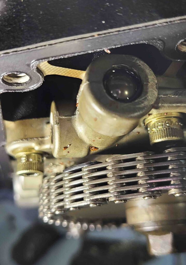
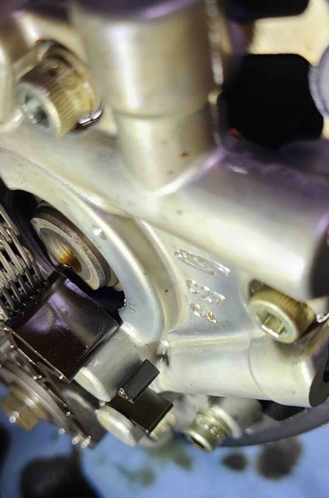
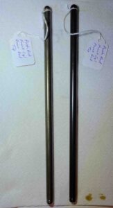
So, the top end disassembly is nearing completion. The rocker box and various internal components came off easily and things looked really good inside. I labeled everything including the orientation of the pushrods and the bolts according to their original positions. The service manual hints were basically intended to keep mated surfaces together for reassembly. This should minimize excessive wear and premature failure that would occur if the wear surfaces were to be mixed up. For example, each pushrod is already broken in to its particular lifter and rocker arm. Some photos from the process are included below.

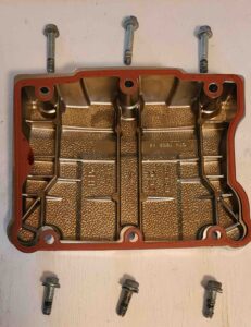
Rocker box cover removed
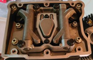
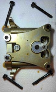
Rockers and breather assembly
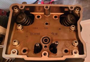
Rockers removed
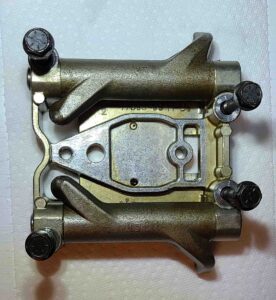
Rocker support plate – top view
Rocker support plate – bottom view
Pushrods
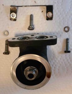
Oil filter mount removed

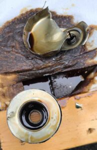
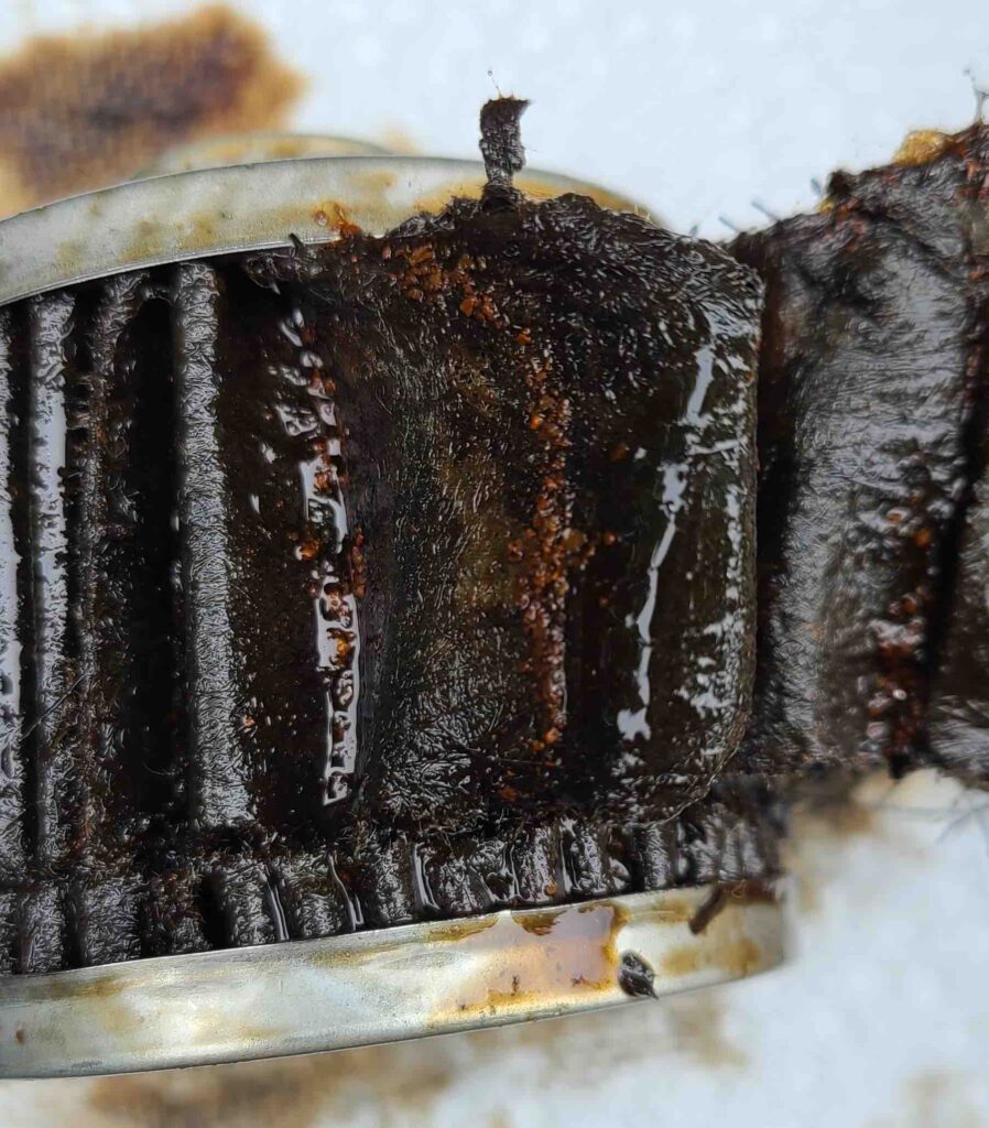
As an aside, I opened up the oil filter to take look. That turned out to be a messy and non-trivial task. I wanted to make a nice slice around the circumference of the filter to access the filter media, but there was a lot of residual oil that made it challenging. In the end, I used two pairs of locking pliers to tear the casing apart. Not pretty, but functional. The media had debris in every fold similar to the flecks found in the oil pan and the oil. Fortunately, I didn’t find much else of interest in the media, so there’s that. See photos below.

Open oil filter casing
Debris in oil filter media

Cheers,

Howard

Where an engine used to be

JMJ

Greetings! Welcome back to the shop! The last few days have been busy, so let’s get to it.

After removing the exhaust system, the main work was identifying and disconnecting the various wires and hoses still attached to the engine. This included the breather hose, oil hoses, voltage regulator, stator cable, crankshaft position sensor, oil pressure sender, and horn.

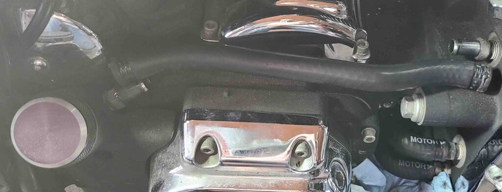
The breather hose connects the crankcase to the oil tank at the fill neck. It was easy enough to find, and the clamps came free with a bit of persuasion, but the hose was very stiff. Instead of tucking it out of the way behind the transmission-to-engine flange, I completely removed it and added that part number (HD-45808-02) and two hose clamps (HD-10249) to the shopping list.

Breather hose – RHS

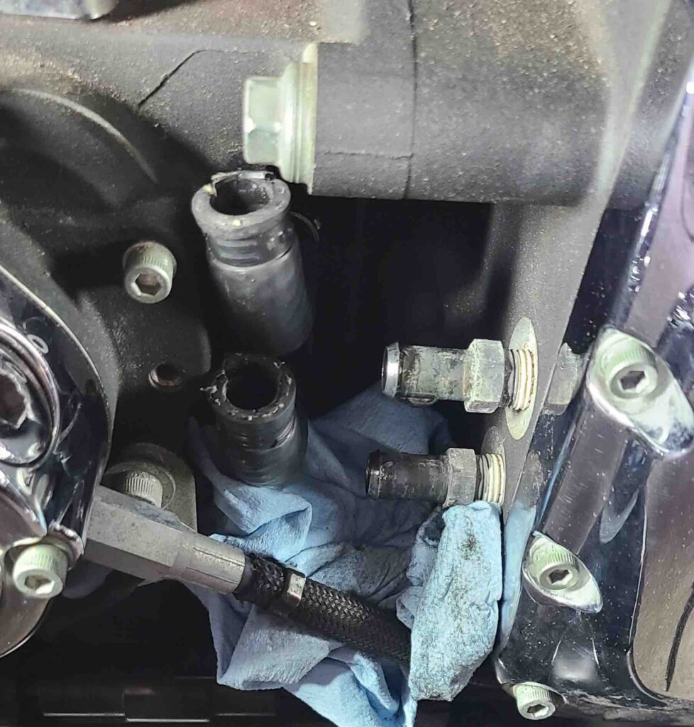
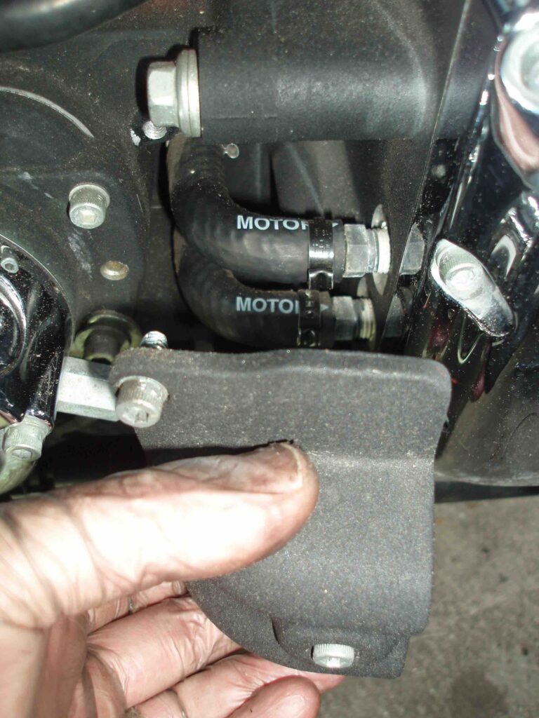
The oil hoses (HD-62726-99) were split a bit at the crankcase fittings. I don’t know if they come like that (doubtful) or if someone needed a bit of relief to make the fit. While the hoses look new and are still supple, they will also be replaced. And four more clamps.

Crankcase oil hoses and fittings

The voltage regulator had its own section in the service manual for removal. The figures were very helpful for tracing out the wires to find the connectors and the ring terminal to which the text referred.

Voltage Regulator Connector and Ring Terminal
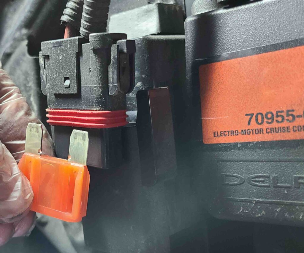
Remove Maxifuse (40A) for Voltage Regulator Removal

The stator connector uses a tongue-and-groove arrangement to mount to the bottom of the voltage regulator. A small cable tie prevents the connector from sliding off the mount. Again, the diagram was very helpful.

Stator Connector beneath Voltage Regulator

Once free, the service manual called for removing the connector and conduit from the stator cables. I fussed with the connector for a bit, then read ahead to see if I could postpone this procedure until stator removal. I could, and I did. Postpone.


The remaining sensors and connectors came off easily and are tagged and stored. I had purchased a 1-1/16 inch open end crow foot to remove the oil pressure sender as recommended in the service manual. I think that a simple wrench of the correct size would have worked as well. I’m not sure why the manual called for the crow foot.

Recent deliveries to the house provided the foam padding and bubble wrap to protect the frame tubes, brake line, brake reservoir, and rocker covers. The short video below shows the engine being removed from the frame to the engine stand on the bench.

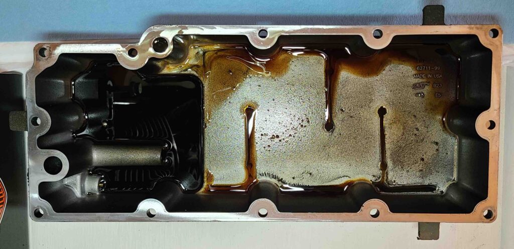
The last major task to this point was removing and inspecting the oil pan. Having previously drained the engine oil, there wasn’t much left. The transmission oil was clean and bright. The oil pan had some debris, but not as much as I expected. I am taking this as good news.

Next steps include removing the induction module, the alternator rotor and stator, and beginning Top End Disassembly. To remove the rocker arm support plate, both lifters on the cylinder being serviced must be on the base circle (or lowest position) of the cam. Says so in the manual. This effectively unloads the valve train to avoid damage to rods, bushings, etc. The funny part is rotating the engine to achieve the correct cam position.

The service manual lists three methods depending on whether the primary cover is installed, the primary cover is removed, or the engine is mounted in an engine stand. The manual explicitly cautions against putting a socket on the crank or primary cam sprocket flange bolt. Bad things can happen. Since we’re on the engine stand, the procedure is well-defined – you make a special tool by welding a used or discarded compensating sprocket shaft extension to a 13/16 inch socket as shown in the figure in the manual. I love it! No one I called had any shaft extensions to sacrifice, but I did find one on ebay. This may be one of the easier special tools to acquire. It looks like several other will be necessary to manage circlips, piston pins, piston rings, etc.

I think I’ll take some time to thoroughly clean the engine before disassembly. My photos to date have revealed a lot of dirt and grime. Embarrassing, really. I will also read through all the manuals to make a plan. All things that can be done with a choice beverage close by.

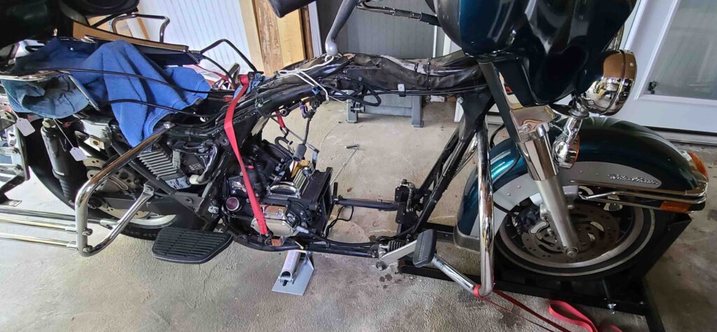
A hole where an engine used to be

Cheers!

It’s Exhausting

JMJ

Greetings! Welcome back! Today, we’re removing exhaust, finishing the removal of the primary chain case, and pulling various connector and cables.

The primary chain case removal stalled a bit when I couldn’t quite get a good bite on the Allen screw mounting the starter. I decided to wait until the exhaust system was out of the way to get a straighter engagement of the tool to the screw. I am really trying to avoid stripping out bolts and screws on removal. 

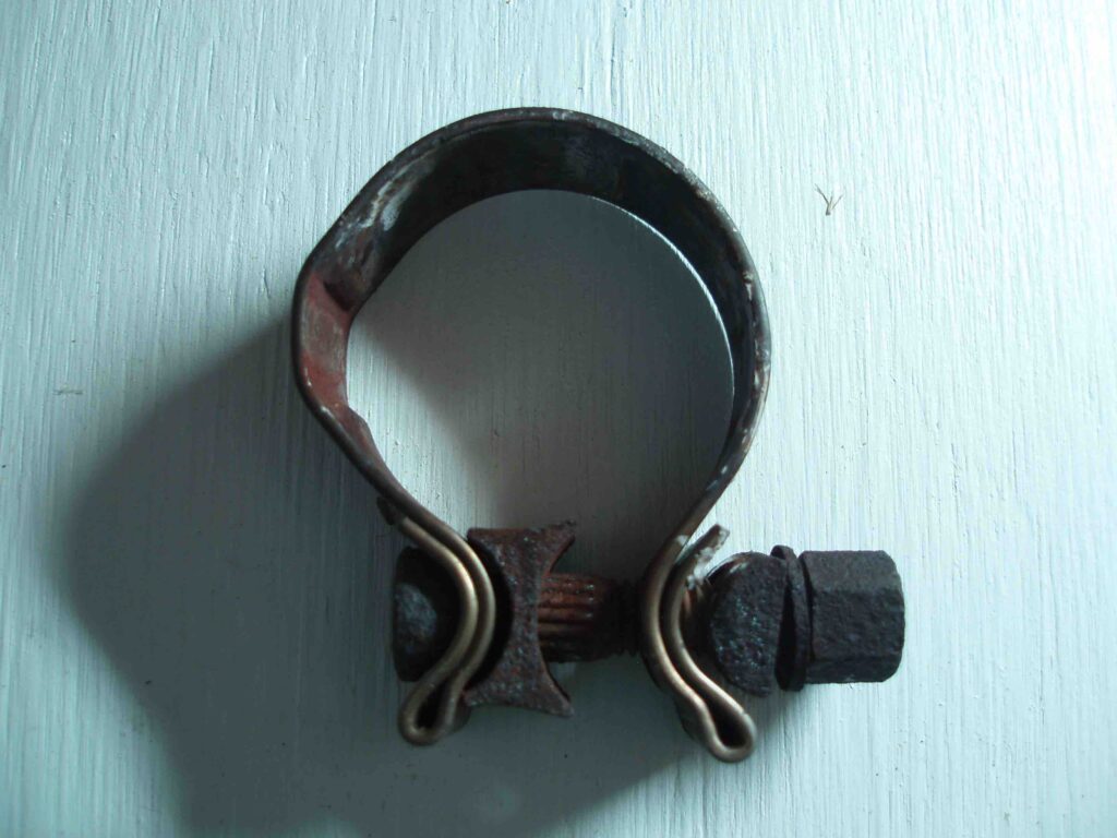
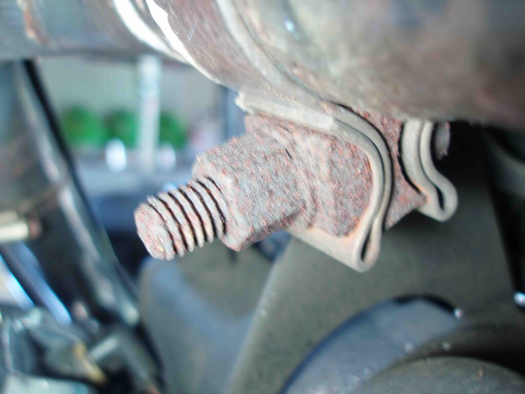
The exhaust system removal basically involves pulling the heat shields, removing the supports, loosening clamps, and un-mounting the headers. Despite the corrosion that had formed on the various high temperature components, the process only took a bit of P B Blaster penetrating oil. The removal process takes the exhaust system off in major assemblies with the header and mufflers left intact. This reduces the expense of replacing the TORCA clamps. Having never seen a TORCA clamp before, I took a couple of photos.

TORCA Clamp
TORCA Clamp on Crossover Exhaust Header

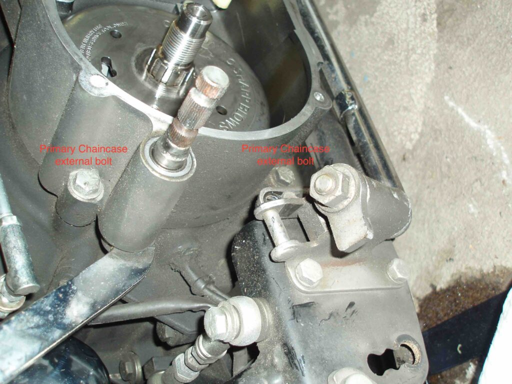
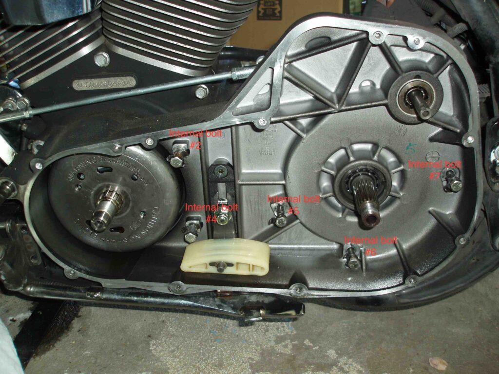
With the exhaust out of the way, the primary chain case removal proceeded very smoothly. I looked ahead to the torquing sequence for the chain case bolts and loosened them in reverse order of tightening on installation. I am trying to leave bolts and screws in place (i.e., lightly threaded into the fastener) to avoid having a box full of nuts and bolts to sort through when the time comes to re-assemble.

Primary Chaincase External Bolts
Primary Chaincase Internal Bolts
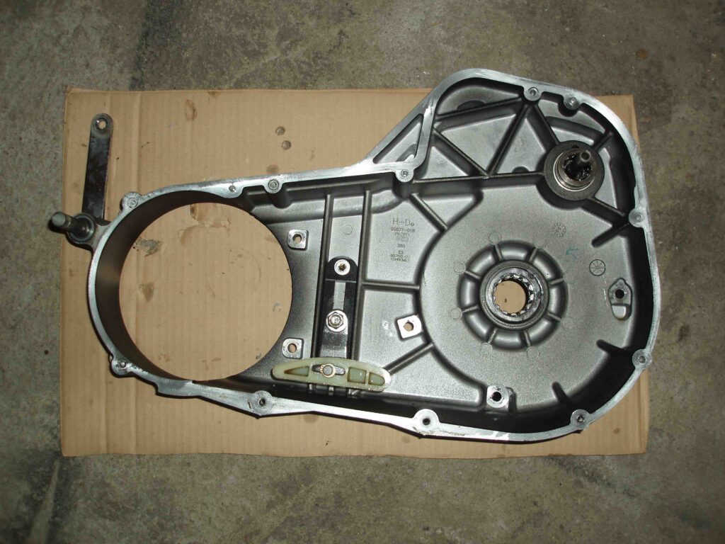
Primary Chaincase removed
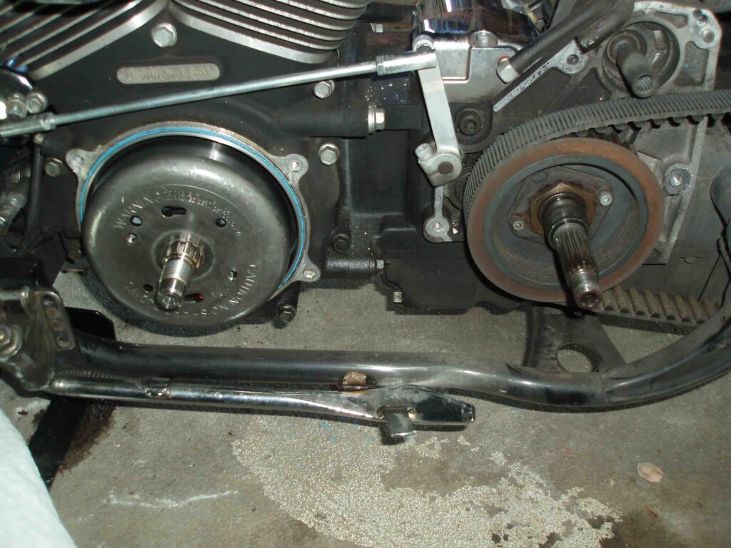
Under the Primary Chaincase

I also purchased a bunch of small tie-on tags to label the components as I removed them. I tagged each piece with the page number, step number, and name of the item before putting it away for re-assembly. As I was working on the right-hand side of the motorcycle, I noticed a connector floating near the rear fender and wondered where it belonged. In time, it came to me that this was the fuel tank harness connector that had been removed when the tank was removed. I tagged it and freed up a few memory cells for other tasks. Tag as you go. I am also making notes in my service manual about the size of wrenches, sockets, etc. that are used to accomplish each step. 

The various connectors around the throttle body were a pain to sort out, but all are free now. Fortunately, the connectors appear to be color-coded, so the photographs that I took along the way should help with reassembly. Of note, the throttle cables were a pain to remove. I did eventually get them free, but will likely replace both cables as a result of the kinks I put in the cables while trying to remove them. 

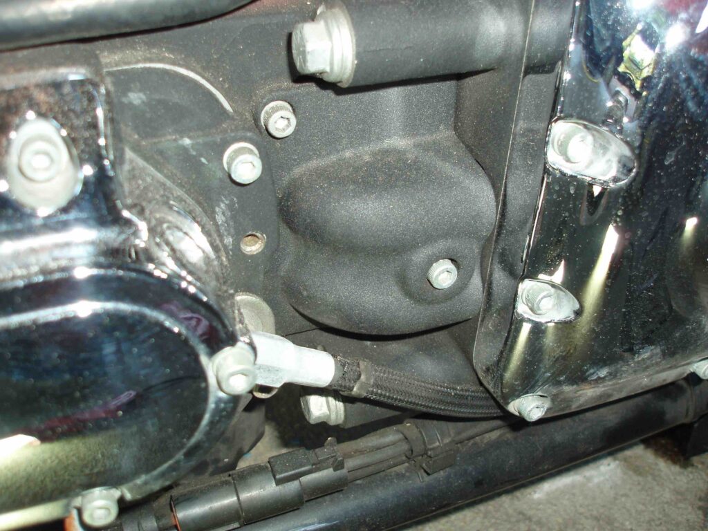
I stopped with the removal of the “oil hose cover”. The service manual gave a clue by specifying that the cover had two Allen screws holding it in place. Photos below.

Engine Oil Hose Cover
Engine Oil Hose Cover Removed

The position of the hose clamps would make a pair of fencing pliers handy, but I don’t have that tool, so I’ll have to figure out another technique for removing the clamps. At this point, my back told me that oil related tasks could wait until next time.

Cheers!